Mechanical installation, Electrical installation – Banner Interface Modules User Manual
Page 3
t
1
1
2
2
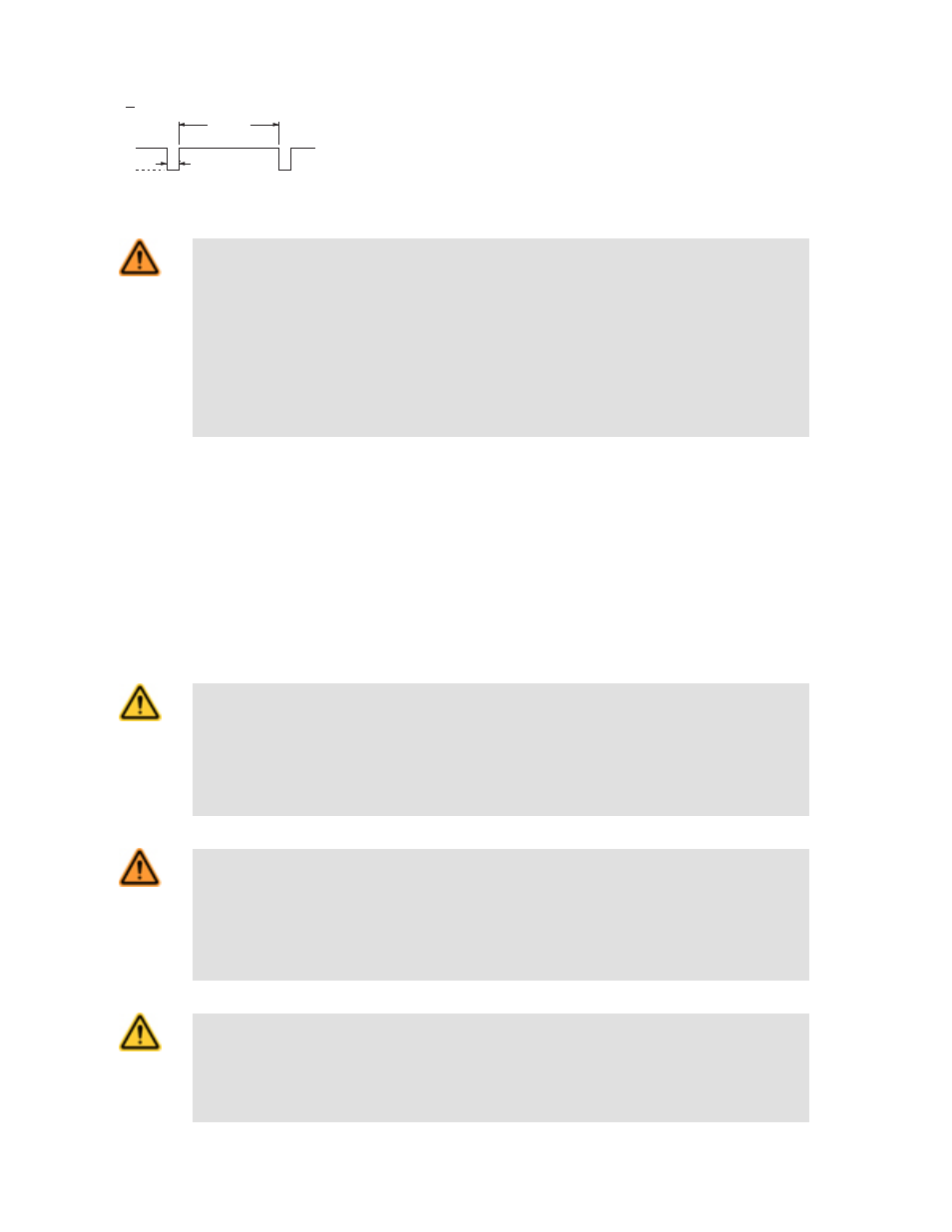
+24V dc
0V dc
> 500
t
t
t
(500 µs max.)
Figure 2. Requirements for pulsed output signals from a primary safety device
WARNING: Not for use as a stand-alone safety module.
1. DO NOT connect E-stop switches, 2-hand control actuators/switches, safety interlock switches, or
similar devices directly to this Interface Module.
2. ALWAYS connect terminals Y1-Y2 and Y3-Y4 of this Interface Module to the monitoring input of the
primary safety device that controls it.
This Module does not have the circuitry required to perform a self-check. A single fault inside the unit or in
external devices (like switches or E-stop buttons) can go undetected and create an unsafe condition. Fail-
ure to properly connect this Interface Module to a primary safety device with a monitoring function could
result in serious injury or death.
Mechanical Installation
The Safety Module must be installed inside an enclosure.
It is not designed for exposed wiring. It is the user’s responsibility to house the Safety Module in an enclosure with NEMA 3 (IEC IP54)
rating, or better. The Safety Module mounts directly to standard 35 mm DIN rail.
Heat Dissipation Considerations. For reliable operation, ensure that the operating specifications are not exceeded. The enclosure must
provide adequate heat dissipation, so that the air closely surrounding the Module does not exceed the maximum operating temperature
stated in the Specifications. Methods to reduce heat build-up include venting, forced airflow (e.g., exhaust fans), adequate enclosure
exterior surface area, and spacing between modules and other sources of heat.
Electrical Installation
CAUTION: Shock Hazard
Always disconnect power from the Banner device and the guarded machine before making any connec-
tions or replacing any component. Electrical installation and wiring must be made by qualified personnel
and must comply with the NEC (National Electrical Code), ANSI NFPA79 or IEC 60204-1 and -2, and all
applicable local standards and codes. Use extreme caution to avoid electrical shock at all times. Seri-
ous bodily injury or death could result.
WARNING: Safety Categories
The level of safety circuit integrity can be greatly impacted by the design and installation of the safety
devices and the means of interfacing of those devices. A risk assessment must be performed to deter-
mine the appropriate safety circuit integrity level or safety category as described by ISO 13849-1
(EN 954-1) to ensure that the expected risk reduction is achieved and that all relevant regulations
and standards are complied with.
CAUTION: When FSD1 switches +24V dc and FSD2 switches 0V dc (Figures 4 and 5), a short circuit
between the wires leading to S1, S2, S3 and S4 is detected immediately and K1 and K2 de-energize.
However, a short circuit can result in a high current through the FSD1 and FSD2 contacts, so the current
coming from the 24V dc supply connected to FSD1 and FSD2 must be fused or limited to 6 amps max.
Otherwise, damage to the primary safety device may result.
IM-T-9A and IM-T-11A Interface Modules
P/N 062822 Rev. D
www.bannerengineering.com - tel: 763-544-3164
3