Banner Interface Modules User Manual
Page 5
Safety Output
EDM1
EDM2
Safety Output
+24V dc
0V dc
Y2
Y1
Y3
+
13
14
23
24
33
34
Machine
Control
Feedback (optional)
IM-T-9A
Primary
Safety
Device
Y4
MPCE
1
MPCE
2
MPCE2
MPCE1
S3
K2
S4
K1
K2
K1
S2
S1
+
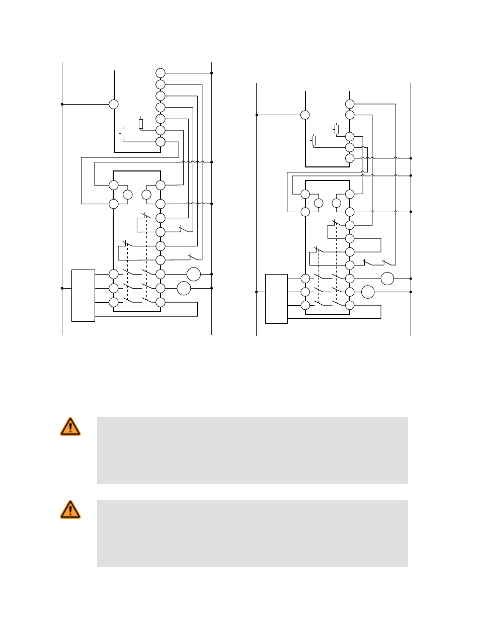
Figure 5. Generalized hookup to a 2-channel primary safety
device with two current-sourcing safety outputs and two mon-
itoring inputs.
EDM
+24V dc
0V dc
+
+
14
23
24
33
34
Machine
Control
Feedback (optional)
IM-T-9A
Primary
Safety
Device
MPCE
1
MPCE
2
MPCE2
MPCE1
Y2
Y1
Y3
Y4
Safety
Output
Safety
Output
S4
K2
K1
K2
S3
S1
K1
S2
+
+
13
Figure 6. Generalized hookup to a 2-channel primary safety
device with two current-sourcing safety outputs and one mon-
itoring input.
Although this hookup shows model IM-T-9A, the hookup for model
IM-T-11A is identical.
Although this hookup shows model IM-T-9A, the hookup for model
IM-T-11A is identical.
WARNING: Use of Arc Suppressors
If arc suppressors are used, they MUST be installed as shown across the coils of the Machine Primary
Control Elements (MPCEs). NEVER install suppressors directly across the output contacts of the
Safety Module. It is possible for suppressors to fail as a short circuit. If installed directly across the
output contacts of the Safety Module, a short-circuited suppressor will create an unsafe condition
which could result in serious injury or death.
WARNING: Wiring of Arc Suppressors
If arc suppressors are used, they MUST be installed as shown across the actuator coil of the stop
control elements (MSCs or MPCEs). NEVER install suppressors directly across the output contacts
of the Safety Device or Module. It is possible for suppressors to fail as a short circuit. If installed directly
across the output contacts, a short-circuited suppressor will create an unsafe condition which could
result in serious injury or death.
IM-T-9A and IM-T-11A Interface Modules
P/N 062822 Rev. D
www.bannerengineering.com - tel: 763-544-3164
5