Hookup diagrams, Two-hand control type iiic – Banner DUO-TOUCH Run Bar with STB Buttons User Manual
Page 6
K = 63" per second,
T
s
= 0.50 seconds (measured by a stop-time measuring device)
T
r
= 0.035 seconds
T
h
= 0.020 seconds
D
s
= K × (T
s
+ T
r
+ T
h
)
= 63" (0.50 + 0.035 + 0.020)
= 35"
In this example, both hand controls must be located no closer than 35" from the nearest hazard point.
Hookup Diagrams
Cabled models only are shown. Quick-disconnect wiring is functionally identical. Connection of dc power is without regard
to polarity.
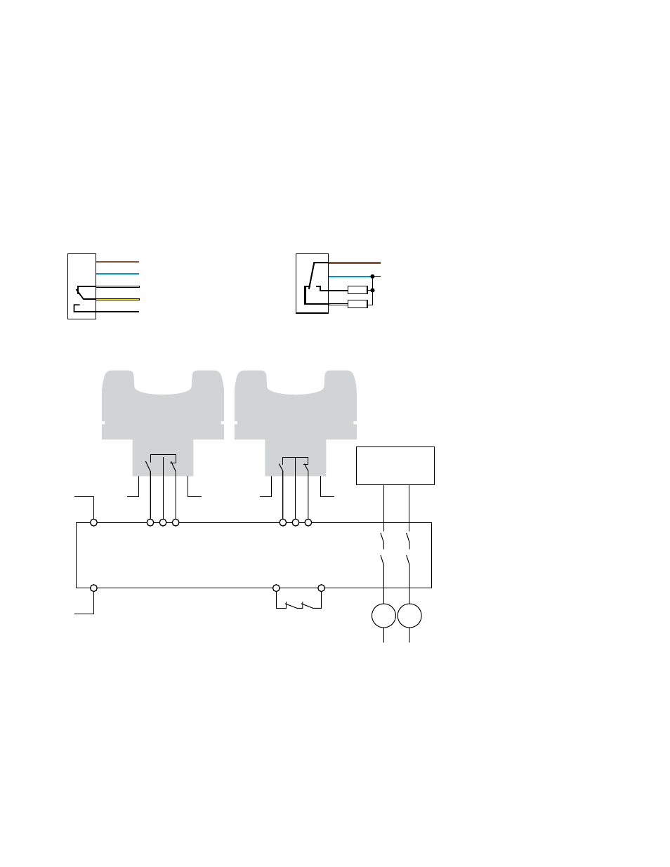
Electromechanical Relay Output Models
PNP (Sourcing) Solid-State Output Models Wiring Key
1
3
2
5
4
Supply Voltage*
(see Specifications)
N.C.
C
N.O.
* NOTE: Connection of dc power is without regard to polarity.
3
1
4
2
10-30V dc
–
+
Load
Load
1 = Brown
2 = White
3 = Blue
4 = Black
5 = Gray or Yellow
A
1
K
1
K
2
Inputs
Inputs
MPCE
Feedback
A
2
A
1
A
2
A
1
A
2
Machine
Control
Circuit
Two-Hand Control
Type IIIC
MPCE
1
MPCE
2
Figure 3. Generic interface of a relay-output STB Touch Button to a type IIIC two-hand-control
module
Wiring Key
1 = Two-Hand Control Type IIIC
Module
2 = Inputs
3 = MPCE feedback
4 = Machine control circuit
STB Self-Checking Optical Touch Buttons
6
www.bannerengineering.com - tel: 763-544-3164
P/N 64136 Rev. C