Installation – Banner DUO-TOUCH Run Bar with STB Buttons User Manual
Page 3
The STB outputs are not monitored by the STB circuitry, and have no external device monitoring feedback. Output
monitoring must be accomplished by using an external device, such as a Type IIIC Two-Hand-Control module.
STB Series Touch Button LED Indicators
Power On (green):
Solid when power is applied
Output, Fault (green):
Solid when button is activated
Off when button is not activated
Flashing when a fault condition is detected
STB Series Self-Checking Touch Buttons were designed primarily to provide the self-checking function required in control-
reliable machine cycle initiation applications. STBs also are suitable for use anywhere mechanical push buttons or the
original OTB Touch Buttons are used.
Both the solid-state and relay-output versions have complementary outputs and can be connected to switch power to
equipment as long as the STB’s switching voltage and current limits are not exceeded.
STBs must be connected to a type IIIC Two-Hand-Control circuit module, in most cases, when used to initiate potentially
dangerous machine cycles.
Installation
OSHA and ANSI require that the hand controls be mounted to protect them from accidental or unintentional operation. Use
shields, covers, rings, collars, dividers, or similar protection to prevent accidental switch actuation and to discourage use of
forearms or elbows. European standard ISO 13851 (EN 574) includes a detailed discussion of approaches to protection of
hand controls. The hand controls must be arranged far enough apart so that the operator cannot operate both hand
controls by the use of one arm. Typically, this distance is not less than 550 mm (21.7") in a straight line, but using guards
or alternate mounting arrangement can allow shorter distances, per ISO 13851 (EN574). This standard also recommends
that hand controls be arranged on a horizontal (or nearly horizontal) surface that is 1,100 mm (43.3") above the floor.
Consider ergonomic principles to avoid unnecessary fatigue in the installation of the hand controls. Install the touch
buttons at a height and in a location that will be comfortable for the user.See ISO 13851 (EN574) Two-Hand Control, ANSI
B11.TR1—Ergonomic Guidelines, and EN894— Safety of Machinery—Ergonomic Requirements—Control Actuators for
further information.
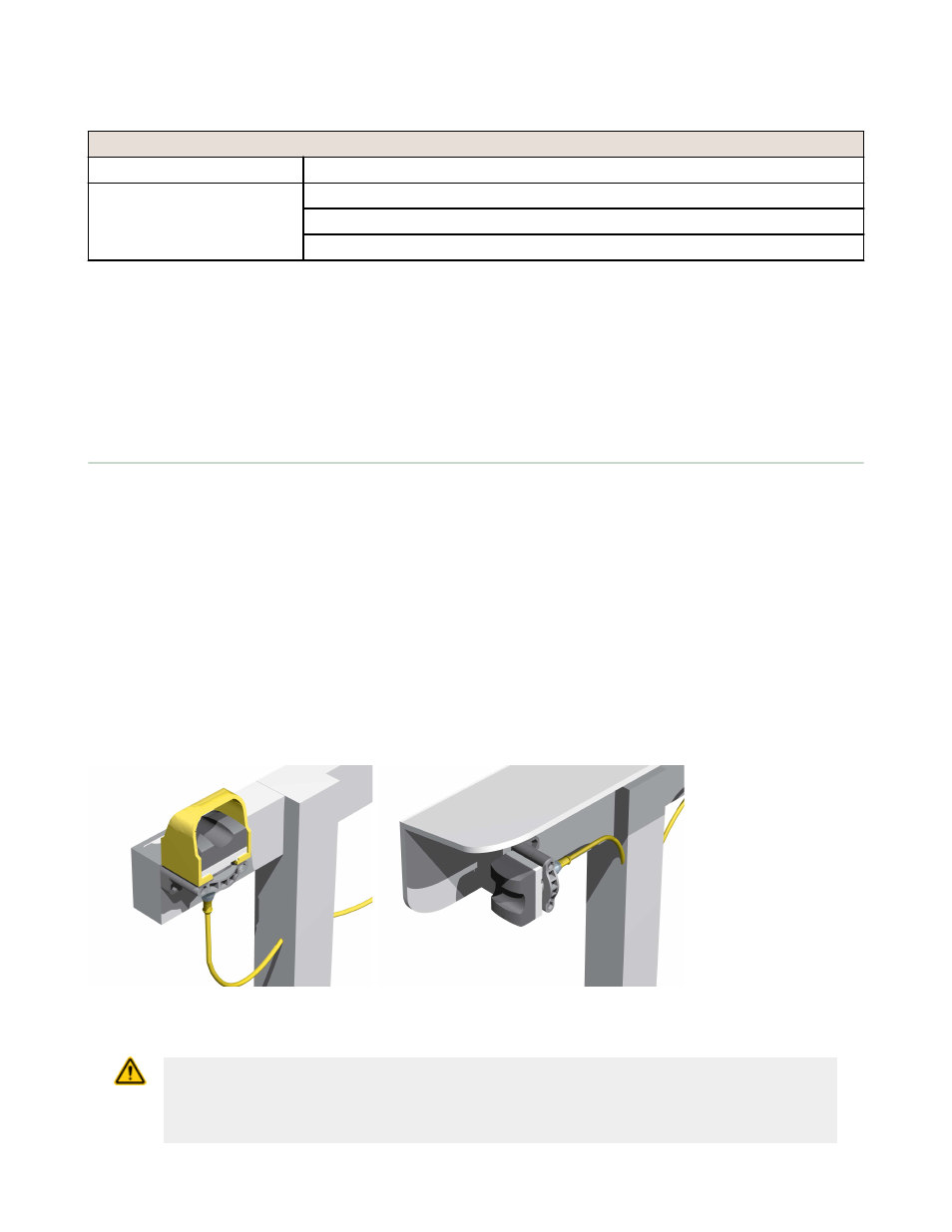
The following figure shows two methods for mounting the touch buttons, to prevent accidental switch actuation. When
mounting them on top of the control bar, the protective field covers should be in place, as shown; or for added protection,
mount the touch buttons sideways under and/or behind a protective hood, rather than on top of the bar, removing the
field covers. This side mount prevents an object from being left in the path of the beam, intentionally bypassing the
safeguard. In addition, shields, covers, rings, collars, dividers, or similar protection may be used to prevent accidental
switch actuation.
Figure 2. Protect STB touch buttons to prevent defeat or inadvertent actuation
CAUTION: Install Hand Controls to Prevent Accidental Actuation
Total protection for the two-hand control system from defeat is not possible. However, the user is
required by U.S. and International standards to arrange and protect hand controls to
minimize the possibility of defeat or accidental actuation.
STB Self-Checking Optical Touch Buttons
P/N 64136 Rev. C
www.bannerengineering.com - tel: 763-544-3164
3