Auto reset manual reset, Wiring drawings, Figure 4. wiring for 2-channel e-stop applications – Banner ES-FA-6G Safety Module User Manual
Page 8
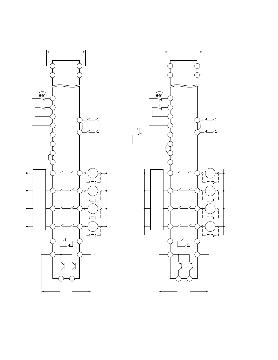
Wiring Drawings
*
*
*
*
MSC1
E-Stop Switch
MSC3
MSC2
MSC Monitor
Contacts
or Jumper for No
Monitoring
MSC Monitor
Contacts
or Jumper for No
Monitoring
L2
MSC1
MSC2
Machine
Master Stop
Control Elements
K1
A
6A max.
6A max.
6A max.
K2
A
K1
B
K2
B
K1
C
K2
C
MSC3
13
14
23
24
33
34
S32
S31
S21
S11
S12
S22
L1
Machine
Control
Circuits
MSC4
S34
S33
S32
S35
*
Arc Suppressors
(see
WARNING
)
6A max.
K1
D
K2
D
MSC4
43
44
5A max.
K1
E
K2
E
51
52
Non-safety
Auxiliary Monitor
Contact
Y31
Y30
Non-safety
Monitor Outputs
100 mA max. each Output
Outputs
Energized
Power Supply
Fault
Outputs
Energized
Power Supply
Fault
dc common
+V
12-24V dc
Y32
Y35
Jumper
*
*
MSC1 MSC3
MSC2
L2
MSC1
Machine
Master Stop
Control Elements
K1
A
6A max.
6A max.
6A max.
K2
A
K1
B
K2
B
K1
C
K2
C
13
14
23
24
33
34
S32
S31
S21
S11
S12
S22
L1
Machine
Control
Circuits
MSC4
S34
S33
S32
S35
*
Arc Suppressors
(see
WARNING
)
6A max.
K1
D
K2
D
43
44
5A max.
K1
E
K2
E
51
52
Non-safety
Auxiliary Monitor
Contact
Y31
Y30
Non-safety
Monitor Outputs
100
mA
max.
each
Output
dc common
+V
12-24V dc
Y32
Y35
Jumper
*
*
Reset Switch
MSC2
MSC3
MSC4
E-Stop Switch
115 ac or 230V ac
B2
B1
AC Power shown
A1
A2
(depending on model)
B2
B1
dc
common
+V
DC Power shown
12-24V dc
A1
A2
ES-UA-5A
115V ac
ES-VA-5A
230V ac
ES-UA-5A
12-24V dc
ES-VA-5A
12-24V dc
AC or DC power
connections shown
are valid for either
auto or manual reset.
Auto Reset
Manual Reset
Figure 4. Wiring for 2-Channel E-Stop Applications
ES-UA-5A and ES-VA-5A E-Stop Safety Modules
8
www.bannerengineering.com - tel: 763-544-3164
P/N 122365 Rev. E