Figure 1. switch wiring to safety module, Figure 3. switch electrical connec, Tions for si-gm100xdsh models – Banner SI-QM100 Locking Style Switches User Manual
Page 5: Periodic checks
Safety Switch #1
Safety Switch #2
Input
Channel
#1
Input
Channel
#2
2-channel Safety Module
(2-channel E-stop Module
2-channel Gate Monitor Module, etc.)
Single gate
or guard
32
21
22
31
32
21
22
31
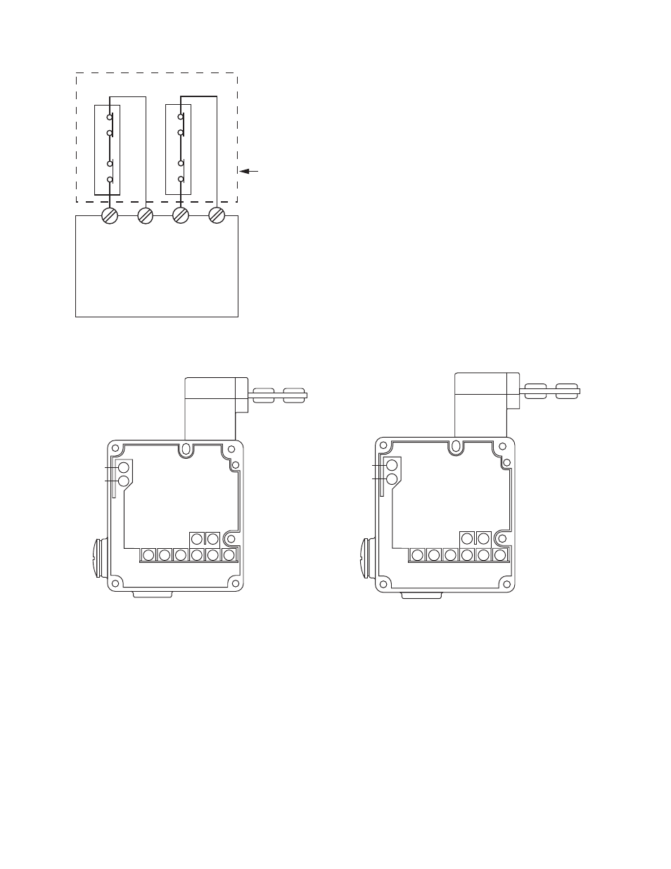
Figure 1. Switch Wiring to Safety Module
Refer to the installation instructions provided with the safety mod-
ule for information regarding the interface of the safety module to
the machine stop control elements.
Connect two redundant safety switches per interlock guard to an
appropriate 2-channel input safety module.
13
E1
E2
14
21
22
31
43
44
32
Solenoid
Voltage
Figure 2. Switch Electrical Connections for SI-GM100xG Mod-
els
11
E1
E2
12
21
22
31
43
44
32
Solenoid
Voltage
Figure 3. Switch Electrical Connections for SI-GM100xDSH
Models
Periodic Checks
Safety switches should be checked at each shift change or machine setup by a designated person for:
1. Breakage of the switch body or actuator,
2. Good alignment and full engagement of the actuator with the receptor,
3. Confirmation that the safety switch is not being used as an end stop,
4. Loosening of the switch or actuator mounting hardware, and
5. Verification that it is not possible to reach any hazard point through an opened guard (or any opening) before hazardous machine
motion has completely stopped.
In addition, a qualified person should check for the following on a periodic schedule determined by the user based upon the severity of
the operating environment and the frequency of switch actuations:
Machine Safety Switches
P/N 049374 Rev. F
www.bannerengineering.com - tel: 763-544-3164
5