Figure 22, Assembling the suppressor – Metrohm 861 Advanced Compact IC User Manual
Page 88
4 Notes - Maintenance - Faults
861 Advanced Compact IC / Instructions for Use 8.861.1033
78
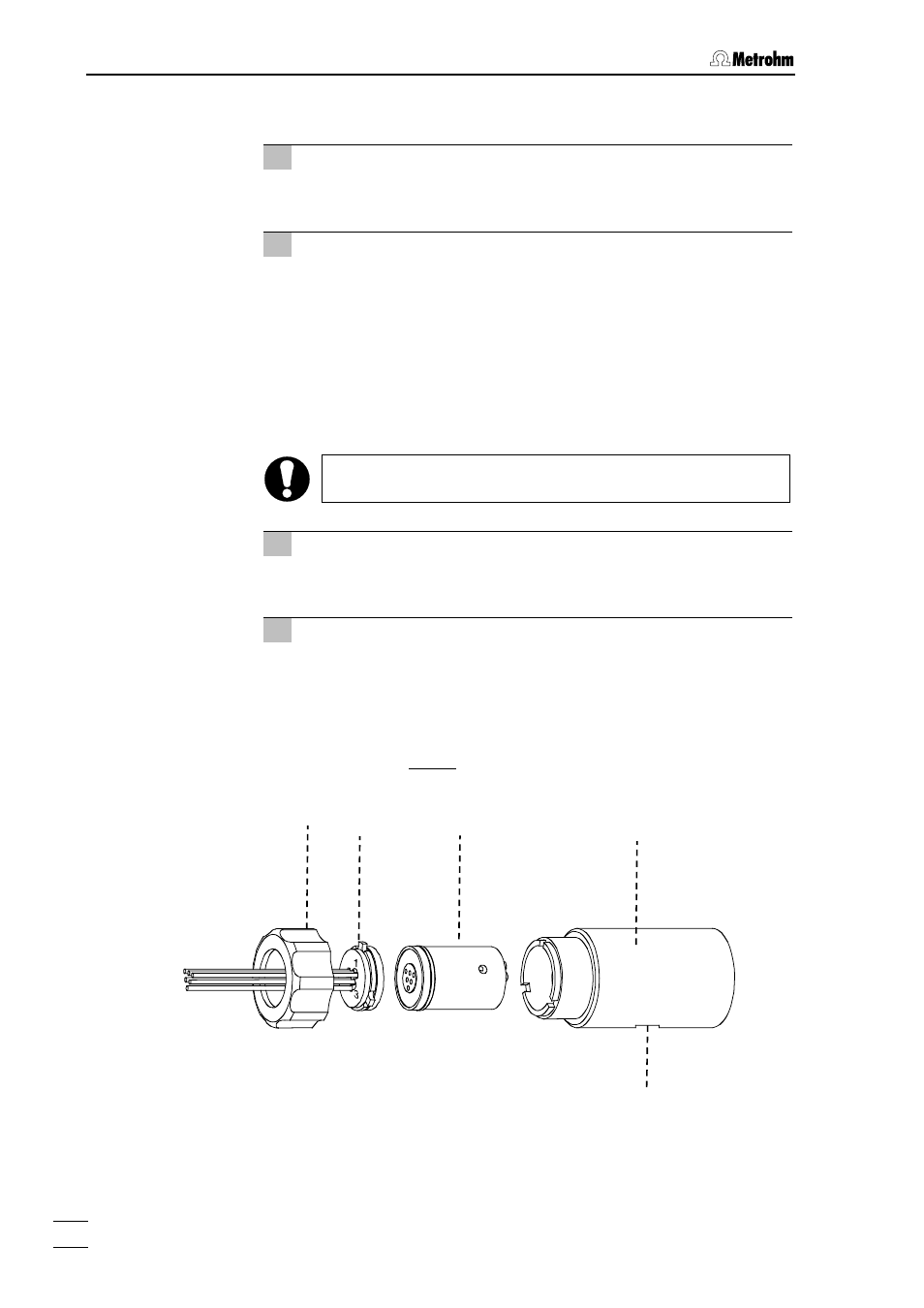
the connection piece 112 (order number 6.2832.010).
4 Clean suppressor rotor
•
Clean the sealing surface of suppressor rotor 113 using a lint-
free cloth and ethanol.
5 Insert suppressor rotor
•
Insert suppressor rotor 113 in suppressor holder 114 in such
a way that the tubing connections at the rear of the rotor fit in
the corresponding openings inside the rotor, and that one of
the three holes in the rotor can be seen from below in one of
the openings of the holder.
•
If the rotor has been inserted correctly, its sealing surface will
be about 4 mm inside the holder. If this is not the case, bring
the rotor into the correct position from below with the aid of a
sharp object (e.g. a screwdriver).
Rotors which are not inserted correctly can be
destroyed
when starting operation.
6 Clean connection piece
•
Clean the sealing surface of connection piece 112 using a lint-
free cloth and ethanol.
7 Insert connection piece
•
Insert connection piece 112 in suppressor holder 114 in such
a way that connection "1" is at the top, and that the three lugs
on the connection piece fit in the corresponding openings of
the holder.
•
Screw nut 111 onto the thread of suppressor holder 114
manually (do not use tools).
Figure 22: Assembling the suppressor
111
112
113
114
115