4 connection of the suppressor module «msm ii, Connection of the suppressor module «msm ii, Figure 17 – Metrohm 861 Advanced Compact IC User Manual
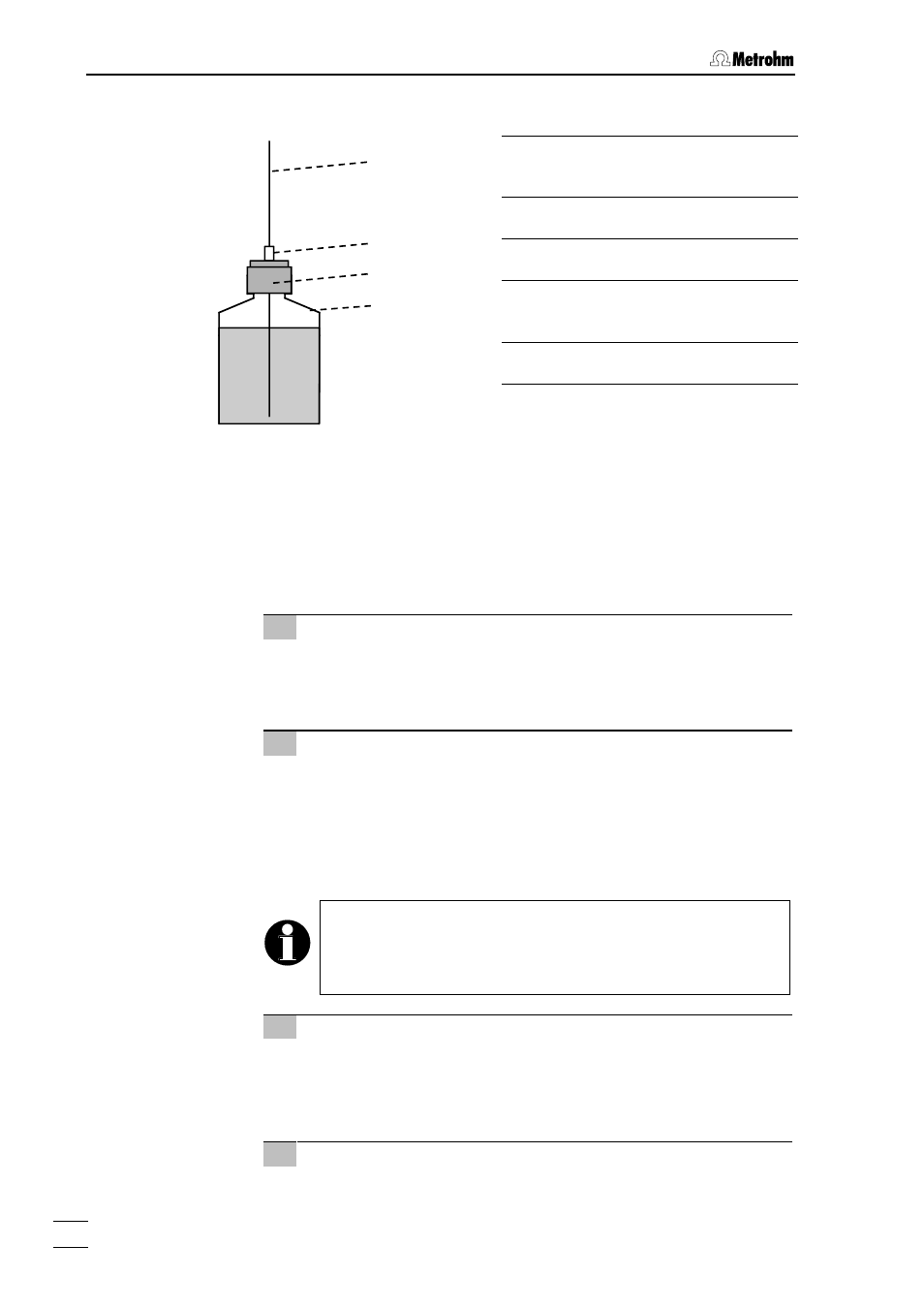
Page 50: Connection of supply bottles, 4 ac, Ction 2.8.4 (see, Peristaltic pump are installed as follows (see, Figure 17 ), To supply bottle 89 (amber glass, Screw bottle attachment 88 on to supply bottle 89
2 Installation
861 Advanced Compact IC / Instructions for Use 8.861.1033
40
Figure 17: Connection of supply bottles
2.8.4
Connection of the suppressor module «MSM II»
The three inlets and outlets numbered 1...3 on the suppressor module
«MSM II» 46 each have 2 permanently mounted PTFE capillaries, which
must be connected as follows (see Figure 16 and Figure 18).
1 Inlet capillary for eluent
•
Screw inlet capillary 82 marked with "Eluent" of suppressor
module «MSM II» 46 to outlet end of separating column 73
using a 6.2744.010 Compression fitting.
2 Outlet capillary for eluent
•
Screw outlet capillary 83 marked with "Detector" of suppres-
sor module «MSM II» 46 to coupling 31 using a 6.2744.010
Compression fitting.
•
Screw inlet capillary 44 of detector block 45 to other end of
For Version 2.861.0040 the outlet capillary
(marked with
"Detector") of suppressor module «MSM II»
should be con-
nected to the inlet
Eluent in
of the 853 CO
2
Suppressor (see
3 Inlet capillary for H
2
SO
4
•
Attach inlet capillary 85 marked with "H
2
SO
4
" of suppressor
module «MSM II» 46 using a 6.2744.010 Compression fitting
to the PEEK Coupling 81 connected to the rear pump tubing
4 Outlet capillary for H
2
SO
4
•
Pull outlet capillary 87 marked with "Waste" of the suppressor
54 Compression fitting
75 Aspirating tubing for H
2
76 Aspirating tubing for H
2
SO
4
88 Bottle attachment
(6.1602.150)
75/76
54
88
89