Gcu wiring – DJI Z15-GH4 (HD User Manual
Page 15
©2014 DJI. All Rights Reserved.
15
GCU Wiring
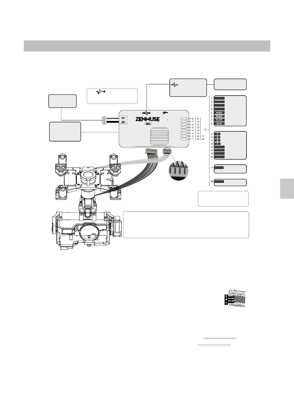
GCU Wiring
WooKong-M users can connect the GCU to any spare CAN-Bus port on the flight control system by using a CAN-
Bus cable. A2 users should connect the GCU to the port labeled CAN1. Alternatively, you may connect the GCU to
the CAN port located on any modules that are already connected to the A2’s CAN1 port via a CAN-Bus cable.
GCU Wiring
A2/WooKong-M
Please refer to your A2/WooKong-M User Manual for all connection and configuration details.
Gimbal Control Unit (GCU)
1. Make sure all ports are accessible when installing your MC so as to facilitate wiring and software configuration.
2. In 3-pin ports, the pins near the nicks are the signal pins.
3. Use the 6-pin cable for the G6 port, and the 10-pin to 9-pin cable for the G9 port.
4. DO NOT cover the heat sinks, and keep them unobstructed at all times.
5. The IMU module is NOT waterproof or oil proof.
RC Receiver
1. The diagram on the previous page shows example connections. The aircraft signal will transmit through the DJI
Lightbridge ground system. After connecting to the Lightbridge, it is not necessary to connect with the RC receiver.
2. Prepare 2 TXs, one for gimbal control, and the other for aircraft control. Refer to the 2-Pilots Solution for more detail.
3. If only one receiver is used for both aircraft and gimbal control, refer to the 1-Pilot Solution for more detail.
4. Setup the Aileron, Elevator, and Rudder channels on the gimbal control TX. The command stick will control
gimbal rotation velocity. The center position is 0, and the end point is maximum velocity in both clockwise
and counter clockwise directions. (The end point is 100%)
5. Choose one 3-position switch/channel to use as the Z15-GH4 Working Mode switch. (MODE)
6. Choose one 2-position switch/channel to use as the camera shutter control switch (SHUT), and another
2-position switch to use as the camera lens orientation switch in Reset Mode (AUX2).
7. Please refer to the A2/Wookong-M User Manual for aircraft control settings. Connect the receiver to the GCU correctly.
Turn to next page to obtain the
correspondence between the GCU
channels and S-Bus/PPM channels.
Battery
Connect the XT60 to the GIMBAL on center frame if S800 EVO used.
Attention that S800 EVO power supply voltage should be within the defined limits (6S), when
using one battery for both S800 EVO and Gimbal power supply.
Refer to S800 EVO User Manual for details.
ROLL
TILT
PAN
MODE
SHUT
AUX1
AUX2
AUX3
A2/WKM
•
•
•
S-Bus
PPM
2-Position Switch
2-Position Switch
3-Position Switch
2-Position Switch
2-Position Switch
2-Position Switch
3-Position Switch
2-Position Switch
USB Port
PC connection for configuration and
firmware upgrades with an USB cable.
Ensure the side with copper contacts is
facing upward towards the heat sinks.
RC Receiver
(Aircraft control)
Battery
(4S~12S)
Wireless Video
Transition Module
Air Unit
RC Receiver
(JR)
8 Channels
RC Receiver
(Futaba/Hitec)
8 Channels
S-BUS Receiver
(Futaba)
PPM Receiver
OR
OR
OR
GH4 HD
G7
G9
G6