Step4 compass calibration, Ompass, Alibration – DJI WooKong-M User Manual
Page 8: Step, Compass calibration, Calibration procedures
©2013-2014 DJI Innovations. All Rights Reserved.
8 |
Step
4
Compass Calibration
Without GPS module, please skip this step. If you use with GPS module, follow step-by-step for calibration.
DO NOT calibrate your compass where there is strong magnetic interference, such as
magnetite, car park, and steel reinforcement under the ground.
DO NOT carry ferromagnetic materials with you during calibration, such as keys or cell phones.
Compass module CANNOT work in the polar circle.
Calibration Procedures
1.
Quickly switch the control mode switch from
GPS Mode
to
Manual Mode
and back to
GPS Mode
for 6 to
10 times. The LED indicator will turn on solid BLUE.
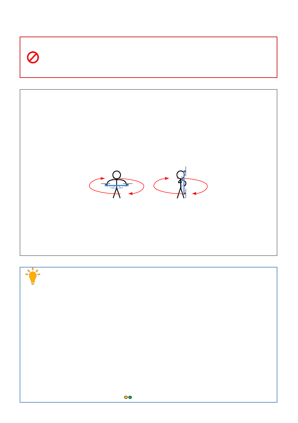
2.
Rotate your Multi-rotor around the horizontal axis (about 360
o
) until the LED changes to solid GREEN,
and then go to the next step.
3.
Hold your Multi-rotor vertically and rotate it
(its nose MUST be downward)
around the vertical axis (about
360
o
) until the LED turns off, meaning the calibration is finished.
4.
The LED indicator will show whether the calibration is successful or not.
If the LED keeps WHITE for 3 seconds, meaning the calibration is successful, and then calibration
mode will exit automatically.
If the LED keeps flashing quickly RED, the calibration has failed. Switch the control mode switch
one time to cancel the calibration, and then re-start from step 1.
1. You don’t need to rotate your multi-rotor on a precise horizontal or vertical surface, but keep at
least 45° difference between horizontal and vertical calibration.
2. If you keep having calibration failure, it might suggest that there is very strong magnetic
interference around the GPS & Compass module, please avoid flying in this area.
3. When to do re-calibration.
The flight field is changed.
The multi-rotor mechanical setup has changed, including the following situations:
a)
If the GPS & Compass module is re-positioned.
b)
Electronic devices added, removed or re-positioned (Main Controller, servos, batteries, etc).
c)
When the mechanical structure of the multi-rotor is changed.
If the flight direction appears shifting (meaning the multi-rotor doesn’t “fly straight”).
The LED indicator often indicates abnormality blinking when the multi-rotor spins. But it is normal
for this to happen only occasionally.
LED blinks yellow and green (
) continually, indicating that the compass data is abnormal.