Installation instructions, Caution – Brandmotion 9002-8601 User Manual
Page 3
INSTALLATION INSTRUCTIONS
8601 Instructions 7-20-12.doc
Page 3 of 4
Step 8: Splice the red, green, and black Video
Display Harness leads into the corresponding
vehicle wires (Note: Soldering recommended or
T-taps as optional connection method).
RECOMMENDED: Attach an eyelet to the black
ground wire.
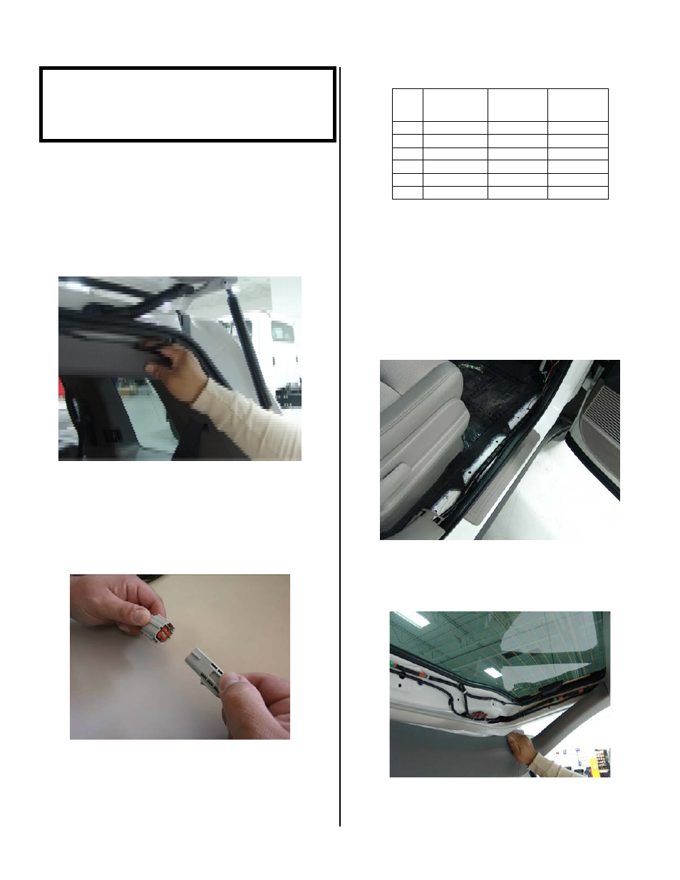
Step 9: Route Camera Harness towards the
side of the vehicle that supplies power.
Step 10: Connect Camera Harness to
supplied Chassis Harness. The optimal location
for this junction may occur at the top of the liftgate
or the inner edge of the trunk depending on vehicle
in which installation is in (Note: most vehicles may
already have existing wires passing through this
area; use this route if at all possible).
Pinout Reference Chart
PIN
#
FUNCTION
CAMERA
HARNESS
COLOR
CHASSIS
HARNESS
COLOR
1
Video (+)
Yellow
White
2
Shield
White
Blue
3
Reverse
Brown
Green
4
Video (-)
Gray
Brown
5
Ground
Black
Black
6
Ignition
Red
Red
Step 11: Route Chassis Harness forward. It
may be necessary to remove sill plates, pillar
covers, seat bottoms, side panels, etc. In some
cases even the seatbelt bolts at the bottom of the
pillars must be removed. (CAUTION: Any bolts
removed for safety devices must be retightened to
manufacturer’s specified torque specifications). Use
a plastic trim removal tool to avoid damage to trim
pieces.
Step 12: Secure Camera Harness to existing
vehicle wiring. This will minimize chance of
binding or otherwise damaging the harness
(RECOMMENDED: Wire Ties or Electrical Tape.)
CAUTION:
Once correct wires have been identified, turn
Ignition key OFF and DO NOT TURN key back ON
until the install has been completed (Step 15).