Installation instructions – Brandmotion 9002-1005 User Manual
Page 4
INSTALLATION INSTRUCTIONS
1005 Instructions 11-11-13.doc
4 of 5
Wire Chassis Harness
27. Use a T15 Torx bit to remove the (2) bolts securing
the driver side knee bolster.
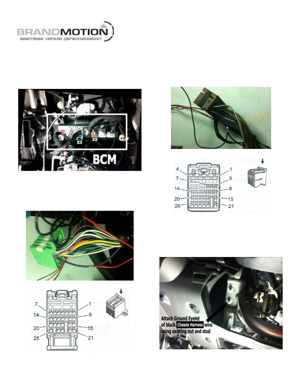
28. Locate the Body Control Module (BCM) below the
dash just to the left of the steering wheel. Note: the
BCM connectors face toward the firewall. (Figure 12)
Figure 12
29. Remove green BCM X3 Connector from the BCM.
(Figure 11). Splice Red Ignition wire of the Chassis
Harness to the Violet/Black wire in Pin 6 of the
connector (Recommended: Solder and cover with
Heat Shrink Tubing. (Figure 13)
Figure 13
Green BCM Connector X3 Pinout
30. Reinsert green BCM X1 connector in the BCM.
31. Remove the brown BCM X5 Connector from the
BCM. (Figure 11) Splice Green Reverse wire of the
Chassis Harness to the Dark Blue/Brown wire in Pin
26 of the connector (Recommended: Solder and
cover with Heat Shrink Tubing. (Figure 14)
Figure 14
Brown BCM Connector X5 Pinout
32. Reinsert brown BCM X5 connector in the BCM.
33. Attach Ground Eyelet of the black Ground wire on
the supplied Chassis Harness to chassis ground
using the stud located behind the knee bolster
indicated in Figure 15.
Figure 15