Installation instructions, Pinout reference chart – Brandmotion 9002-8538 User Manual
Page 8
INSTALLATION INSTRUCTIONS
8538 Instructions 5-27-14.docx
Page 8 of 9
Step 14: Splice the red and green Chassis Harness
leads into the corresponding vehicle wires and the
black wire to chassis ground. (Note: Soldering
recommended or T-taps as optional connection
method). RECOMMENDED: Attach an eyelet to the
black ground wire.
Step 15: Route Camera Harness towards the side of
the vehicle that supplies power.
Step 16: Connect Camera Harness to supplied
Chassis Harness. The optimal location for this junction
may occur at the top of the liftgate or the inner edge
of the trunk. (Note: Most vehicles have existing wires
passing through this area; use this route if at all
possible).
Pinout Reference Chart
PIN
#
FUNCTION
CAMERA
HARNESS
COLOR
CHASSIS
HARNESS
COLOR
1
Video (+)
Yellow
White
2
Shield
White
Blue
3
Reverse
Blue
Green
4
Video (-‐)
Brown
Brown
5
Ground
Black
Black
6
Ignition
Red
Red
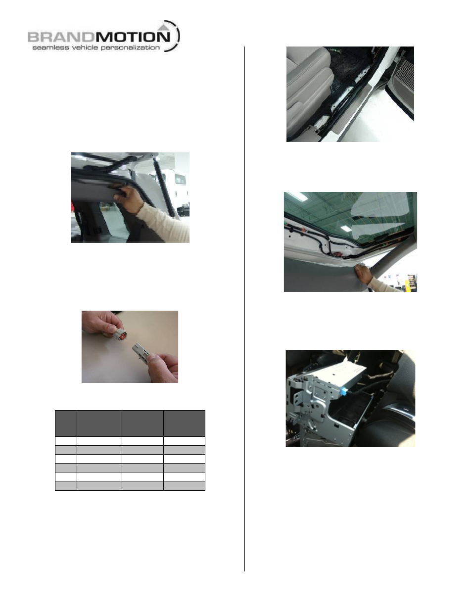
Step 17: Route Chassis Harness forward. It may be
necessary to remove sill plates, pillar covers, seat
bases, side panels, etc. using a Plastic Trim Removal
Tool. In some cases, seatbelt bolts must be removed.
(CAUTION: Any bolts removed for safety devices
must be retightened to manufacturer’s torque
specifications).
Step 18: Secure Camera Harness to existing
vehicle wiring. This will minimize chance of
binding or otherwise damaging the harness.
RECOMMENDED: Wire Ties or Electrical Tape.
Step 19: Use a Plastic Trim Removal Tool, 7
or 10mm Socket, and/ or Phillips
Screwdriver to remove garnish and
fasteners securing the Radio. Remove
radio.
Step 20: Pull the radio out to disconnect
the vehicles 20-pin connector. Caution: Be
careful not to disconnect antenna or other
connection to back of radio.