Installation instructions, Chassis harness connection chart – Brandmotion 9002-8538 User Manual
Page 7
INSTALLATION INSTRUCTIONS
8538 Instructions 5-27-14.docx
Page 7 of 9
using a 1/8” drill bit. NOTE: If your vehicle has a
liftgate panel/trunk trim cover, it must be removed.
Step 5: Drill two 5/16” holes for the camera
mounting bolts and one 5/8” hole for the camera
harness. Use a Deburring Tool or Round File to
smooth edges.
Step 6 (if necessary): Using a 5/8” drill bit, drill an
opening in the trunk or liftgate for the head of the
Camera Harness to pass through. Insert Camera
Harness head through the backside of the hole so
that the gray connector end of the Camera Harness
is inside the trunk or liftgate. (RECOMMENDED:
Protect Camera Harness with a rubber grommet or
by applying a small amount of silicone caulk to the
area that comes into contact with the edges of the
hole. Additional recommendation: If drilling
through sheet metal, apply a Corrosion Inhibitor.)
Step 7: Route head of Camera Harness through the
pass-through you made with the Template.
Step 8: Use a Phillips Screwdriver to remove the
two screws provided in the Camera to secure the
head of the Camera Harness onto the Camera.
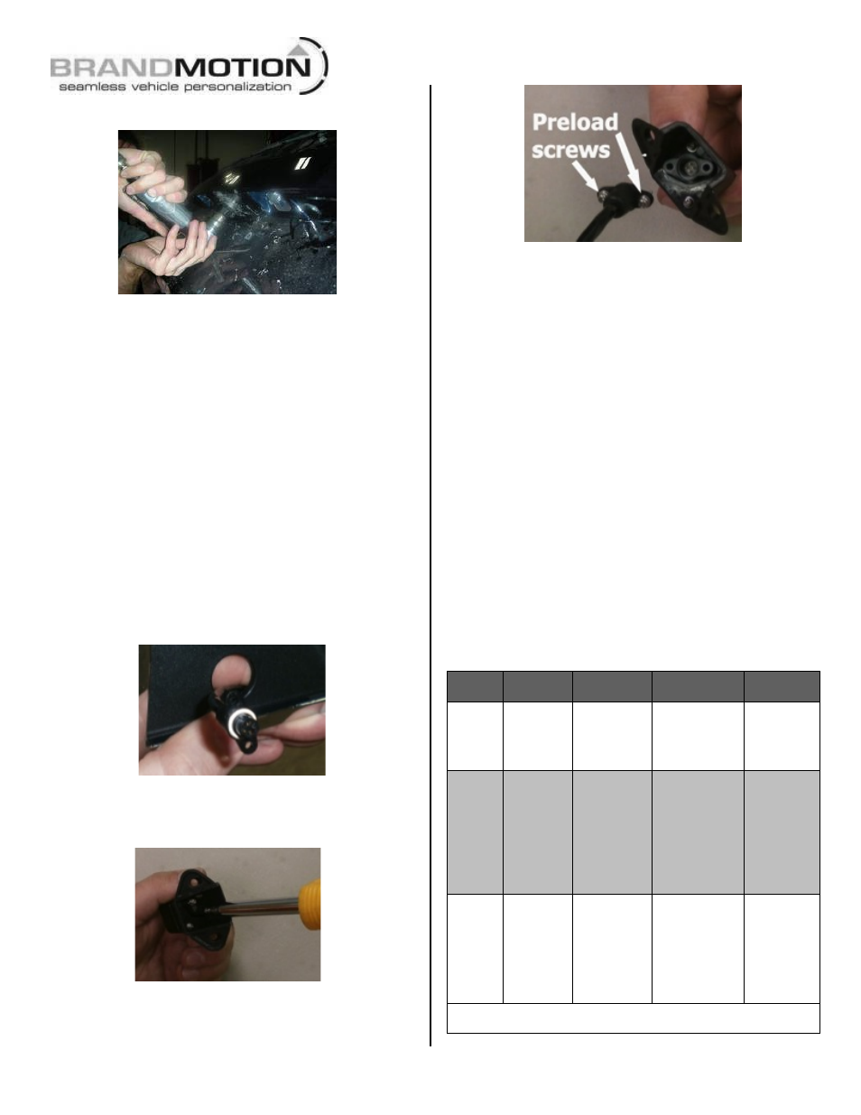
Step 9: Preload the screws into the Camera
Harness connector.
Step 10: Align the Camera Harness head so the
key lines up with the slot in the camera, and plug
in the connector. Snug the supplied screws with a
Phillips Screwdriver to create a watertight seal but
do not over tighten.
Step 11: Mount the Camera using the supplied
hardware. Insert the two Rubber Well Nuts into the
outer 5/16” camera mount holes.
Step 12: Thread the two supplied Bolts through
the Camera Mount and into the Well Nuts using a
Phillips Screwdriver but do not tighten the Bolts all
the way down just yet.
Step 13: Determine location of vehicle Ignition
power and Ground. Using a vehicle specific service
guide/wiring diagram and a multi-meter or
computer-safe test light, locate which side of the
vehicle contains the wires into which you will
connect Chassis Harness wiring (see chart
below).
Chassis Harness Connection Chart
Wire
Color
Polarity
Function
Description
Location
note
Red
12v +
Ignition
controlled
power
This lead
displays 12 volt
+ when the
key is in the
RUN position
Commonly
found on
main
Ignition
harness.
Black
(–)
Ground
Chassis ground
A ground
bolt is
commonly
found in
the front
kick panel
area with
other wires
attached.
Green
12v +
Reverse
trigger
This lead is
activated when
the vehicle is
engaged into
Reverse
Commonly
found in
front kick
panel area
on harness
coming
from rear of
vehicle.*
*If Reverse cannot be located, connect the both the Red and Green
wires to Ignition power.