Installation instructions, Dealer programming instructions – Brandmotion 9002-8532 User Manual
Page 5
INSTALLATION INSTRUCTIONS
8532 Instructions 5-19-14.docx
Page 5 of 5
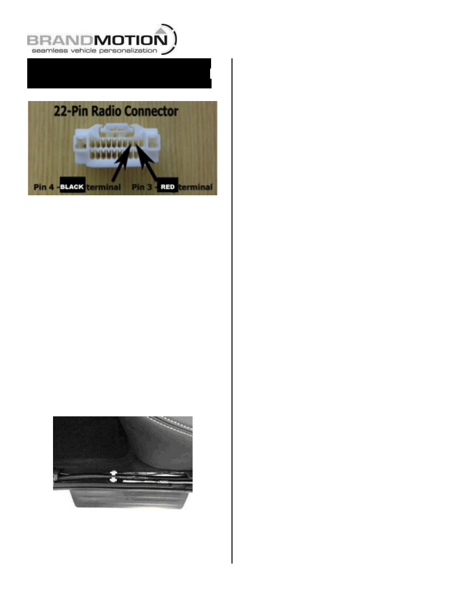
NOTE: If vehicle is NOT equipped with a 22-
pin radio connector (Figure 1), use supplied
White connector to complete Steps 23 & 24.
Figure 1
IMPORTANT: If the White 22-pin connector is
present in the vehicle and Pin 3 and/or Pin 4 are
already populated, remove the terminal(s) using
Delphi Terminal Removal Tool #12094429 or a
Small Flat Watch Repair Screwdriver and isolate
with Electrical Tape.
Step 23: Remove both terminals from chassis
harness. Splice provided loose red wire to chassis
harness red wire and insert terminal into pin
position 3 on the white 22-pin radio connector
(Figure 1) until it clicks securely.
Step 24: Splice provided loose black wire to
chassis harness black wire and insert terminal into
pin position 4 on the white 22-pin radio connector
(Figure 1) until it clicks securely.
Step 25: Connect White 22-pin Connector to radio
along with all remaining radio connectors before
reinstalling radio head unit and all trim removed.
Step 26: Use supplied Wire Ties to secure Chassis
Harness to existing vehicle wiring.
Step 27: Coil any excess Chassis Harness and
secure it to existing vehicle wiring with supplied
Wire Ties.
Dealer Programming Instructions
PARK VIEW REAR BACK-UP CAMERA
VEHICLE CONFIGURATION
Vehicle VIN must be updated with the sales code of the
added accessory in order to enable system functionality.
Using the DealerCONNECT website and the scan tool,
complete the procedure below:
A. Log on to https://dealerconnect.chrysler.com
B. In the “Vehicle Option” screen under “Global Claims
System” category in the “Service” tab, enter the
VIN and add the following sales code: XAC (PARK
VIEW REAR BACK-UP CAMERA) as a “Dealer
Installed Option.”
C. Confirm that the new sales code has been
successfully added to the VIN. With the scan tool
connected to both the internet (via Ethernet port or
wireless connection) and the vehicle, perform the
following steps:
D. Using the scan tool, select VEHICLE PREPARATION
and then select RESTORE VEHICLE
CONFIGURATION.
E. Follow the step by step instructions on the scan
tool to complete the Park View Rear Back-Up
Camera vehicle configuration.
Step 28: Start vehicle and shift into Reverse in
order to check that all connections were made
properly. If all of the connections are correct you
will see the camera image displayed on your
factory display.
Step 29: Adjust camera aim. With the aid of an
assistant, position camera to achieve desired view.
Using a Phillips Screwdriver, tighten Camera Mount
bolts.
Step 29: Reassemble vehicle. Follow your
disassembly steps in reverse order, taking care not
to bind the harness wiring when reinstalling trim.