Installation instructions – Brandmotion 9002-8532 User Manual
Page 4
INSTALLATION INSTRUCTIONS
8532 Instructions 5-19-14.docx
Page 4 of 5
2011 – 2013 Dodge Durango
Location: Remove console to access 12v power outlet wiring harness
and unwrap harness cover to expose wires inside.
Ignition keyed power 12v +
Ground
Splice Red & Green wires from
supplied Chassis Harness (B) to
Dark Blue/Pink wire of 12v
power outlet wiring harness
(12v DC arrow).
Splice Black wire from supplied
Chassis Harness (B) to Black wire
of 12v power outlet wiring harness
(12v DC arrow).
2014 – Current Dodge Durango and Jeep Grand Cherokee
Location: Remove passenger side kick panel to access BCM.
Ignition keyed power 12v +
Ground
Splice Red & Green wires from
supplied Chassis Harness to
Pink/White wire in pin 27 of
black 48 pin connector (E).
See 2011 – 2013 directions.
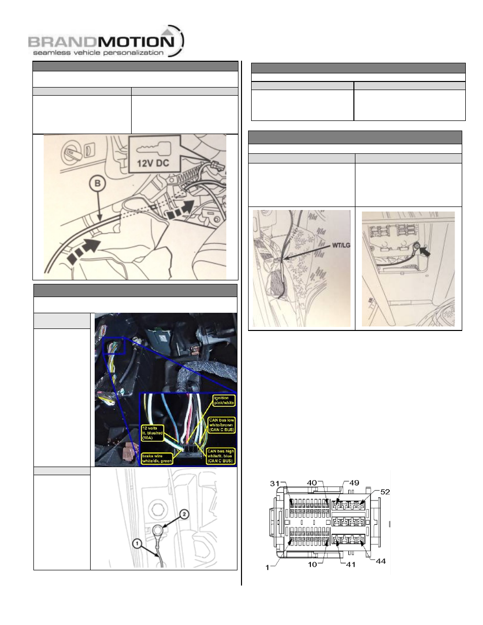
2008 – 2010 Jeep Commander & Jeep Grand Cherokee
Location: Remove driver side kick panel to access main body harness.
Ignition keyed power 12v +
Ground
Splice Red & Green wires from
supplied Chassis Harness to
White/Light Green wire of main
body harness (arrow).
Connect Black wire from supplied
Chassis Harness to lower right fuse
panel mounting screw (arrow).
RECOMMENDED: Attach an
Eyelet to the Black ground wire.
Step 20: Use a Plastic Trim Removal Tool to
remove radio bezel.
Step 21: Unplug all radio connectors from the
radio head unit and set radio aside.
Only complete step 22 for 2014 Dodge
Durango and 2014 Jeep Grand Cherokee
vehicles.
Step 22: Insert terminal from red wire on supplied
chassis harness into position 31 of black 52-pin
radio connector and insert terminal from black wire
on supplied chassis harness into position 32 of
black 52-pin radio connector.
2011 – 2013 Jeep Grand Cherokee
Location: Remove driver side kick panel to access Wireless Ignition
Node wiring harness with black 12-pin connector.
Ignition keyed
power 12v +
Splice Red &
Green wires
from supplied
Chassis Harness
to Pink/White
wire of 12-pin
harness (black
connector).
Ground
Connect Black
wire from
supplied Chassis
Harness (1) to
instrument panel
mounting
bracket
screw (2).
RECOMMENDED:
Attach an Eyelet
to Black wire.