Bowers Group Trimos Mestra Height Gauges User Manual
Page 15
750 50 0001 03
15/28
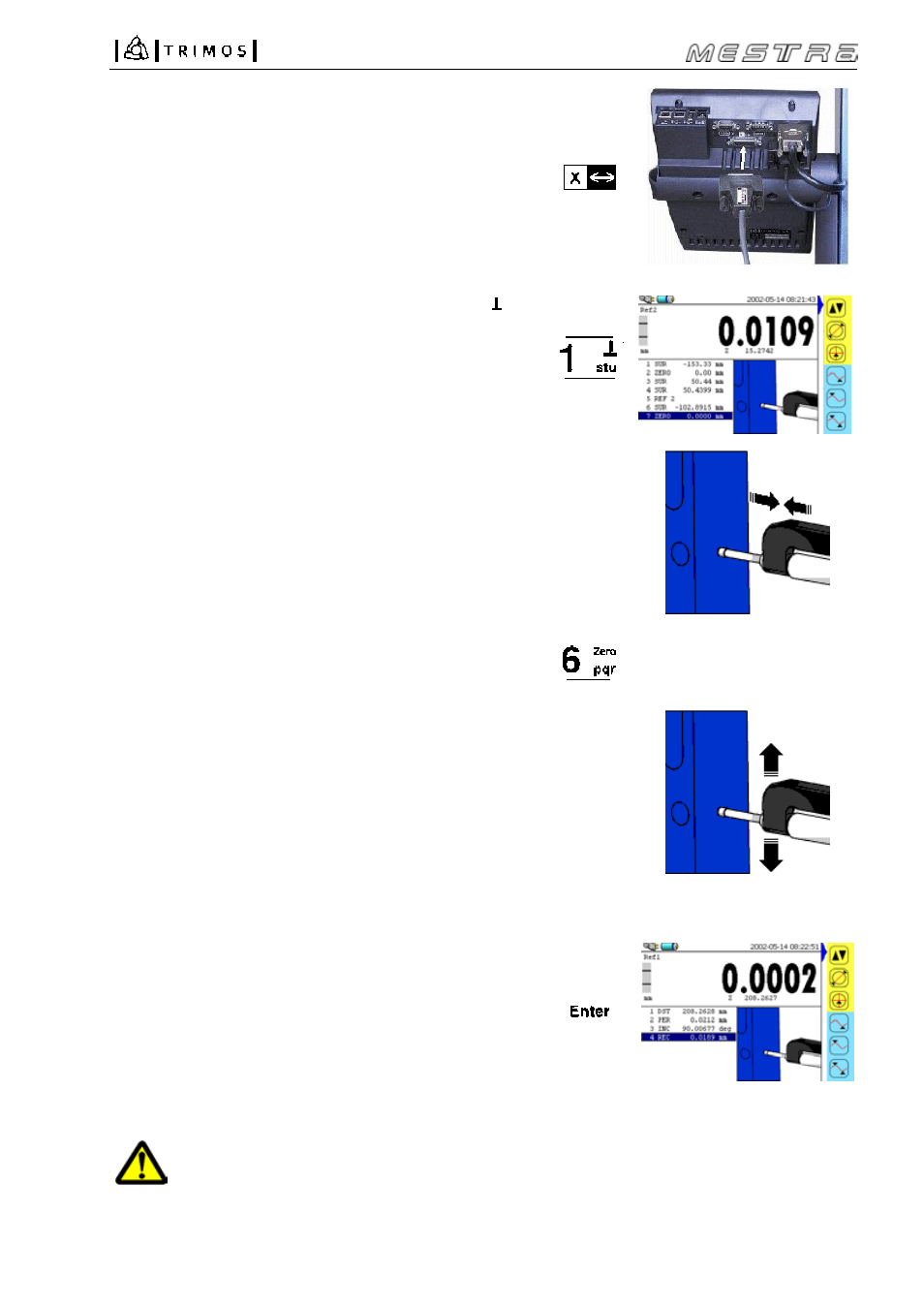
3. Connect the electronic probe to the display unit.
4. Activate the corresponding mode by pressing the key.
The value of the X axis (probe) is displayed in large fat
digits and the value of the Z axis (vertical displacement)
in small digits below the X axis value.
Note:
If no probe is connected, "Error X" will be displayed.
5. Position the part to be checked against the electronic
probe and make sure that a contact is guaranteed over
the entire measuring range. Move the measuring
carriage to its starting position.
6. Set the display at zero by pressing the Zero key.
7. Move the probe slowly along the surface to be checked.
During this motion, the Z axis values (vertical) and the
X axis values (horizontal) are displayed constantly in
direct.
8. The checking completed, press the Enter key to
calculated the squareness deviation, the inclination
and the rectilinearity. All values are stored and
displayed in the buffer as follows:
z Distance
DST
⊥ Squareness
deviation PER
∠ Inclination
INC
— Rectilinearity
REC
It is possible to perform more squareness deviation
measurements at once by repeating the procedure from
point 5 to 8.
As the squareness deviation of the instrument is electronically compensated, the mentioned
deviations must be checked using the Trimos electronic probe. It is not possible to check
squareness deviations using a test indicator or any other system. As an option (on request), we
propose instruments where the squareness deviation has been adjusted mechanically.
X
Z