Rockwell Automation FlexPak Plus NRG DC Drive User Manual
Page 9
8
SECTION 3
INSTALLATION
3.0 General
- This Section outlines the procedures
that are to be followed in order to properly install a FlexĆ
Pak Plus controller.
The dĆc motor should be installed and wired in accorĆ
dance with installation instructions supplied with each
drive.
There are certain general warnings and cautions that
should be kept in mind before planning begins. They
should be considered a general checklist which, iffolĆ
lowed, will minimize installation problems and decrease
assembly time. As a user aid, they are listed here.
DANGER
THIS UNIT SHOULD BE INSTALLED, ADJUSTED
AND SERVICED BY QUALIFIED ELECTRICAL
MAINTENANCE PERSONNEL FAMILIAR WITH
THE CONSTRUCTION AND OPERATION OF
THIS TYPE OF EQUIPMENT. THEY SHOULD
ALSO BE FAMILIARWITH THE POTENTIAL
HAZARDS INVOLVED. IF THIS WARNING IS NOT
OBSERVED. PERSONAL INJURY OR EQUIPĆ
MENT DAMAGE MAY RESULT.
DANGER
BE ABSOLUTELY CERTAIN THAT A GROUND
WIRE FROM THE INCOMING AĆC POWER LINE
IS PROPERLY CONNECTED TO THE CHASSIS
GROUND TERMINAL PROVIDED. WITHOUT
PROPER GROUNDING, PERSONAL INJURY
MAY OCCUR.
WARNING
THE CONTROLLER REQUIRES A THREEĆ
PHASE POWERSUPPLY THAT PROVIDES EIĆ
THER230 VAC OR460 VAC AT 60 HZ, OR220
VAC OR 440 VAC AT 50 HZ. IF CORRECT
VOLTAGE IS NOT AVAILABLE, IT WILL BE
NECESSARY TO INSTALL A TRANSFORMER
BETWEEN THE POWERSUPPLY AND THE
CONTROLLER. DO NOT OPERATE THE FLEXĆ
PAK PLUS CONTROLLERON POWERSUPĆ
PLIES WITH AVAILABLE SHORTĆCIRCUIT CURĆ
RENTS IN EXCESS OF 5000 AMPERES. DAMĆ
AGE TO EQUIPMENT AND PERSONAL INJURY
MAY OCCUR.
WARNING
THE USERIS RESPONSIBLE FORCONFORMĆ
ING WITH THE NATIONAL ELECTRICAL CODE
WITH RESPECT TO MOTOR, CONTROLLER
AND OPERATOR DEVICE INSTALLATION, WIRĆ
ING AND STARTĆUP. THE USER IS ALSO REĆ
SPONSIBLE FORUNDERSTANDING AND APĆ
PLYING ALL OTHERAPPLICABLE LOCAL
CODES WHICH GOVERN SUCH PRACTICES AS
WIRING PROTECTION, GROUNDING, DISCONĆ
NECTS AND OVERCURRENT PROTECTION.
3.1 Layout Guidelines
- This Paragraph lists recĆ
ommended layout procedures common to all FlexPak
Plus controllers.
Guideline 1 - The FlexPak Plus controller is designed
as a panelĆmounted unit. It is to be hung within 10S of
vertical with the rear ofthe Chassis firmly resting against
the mounting surface. (Do not position the Chassis on
a horizontal surface.)
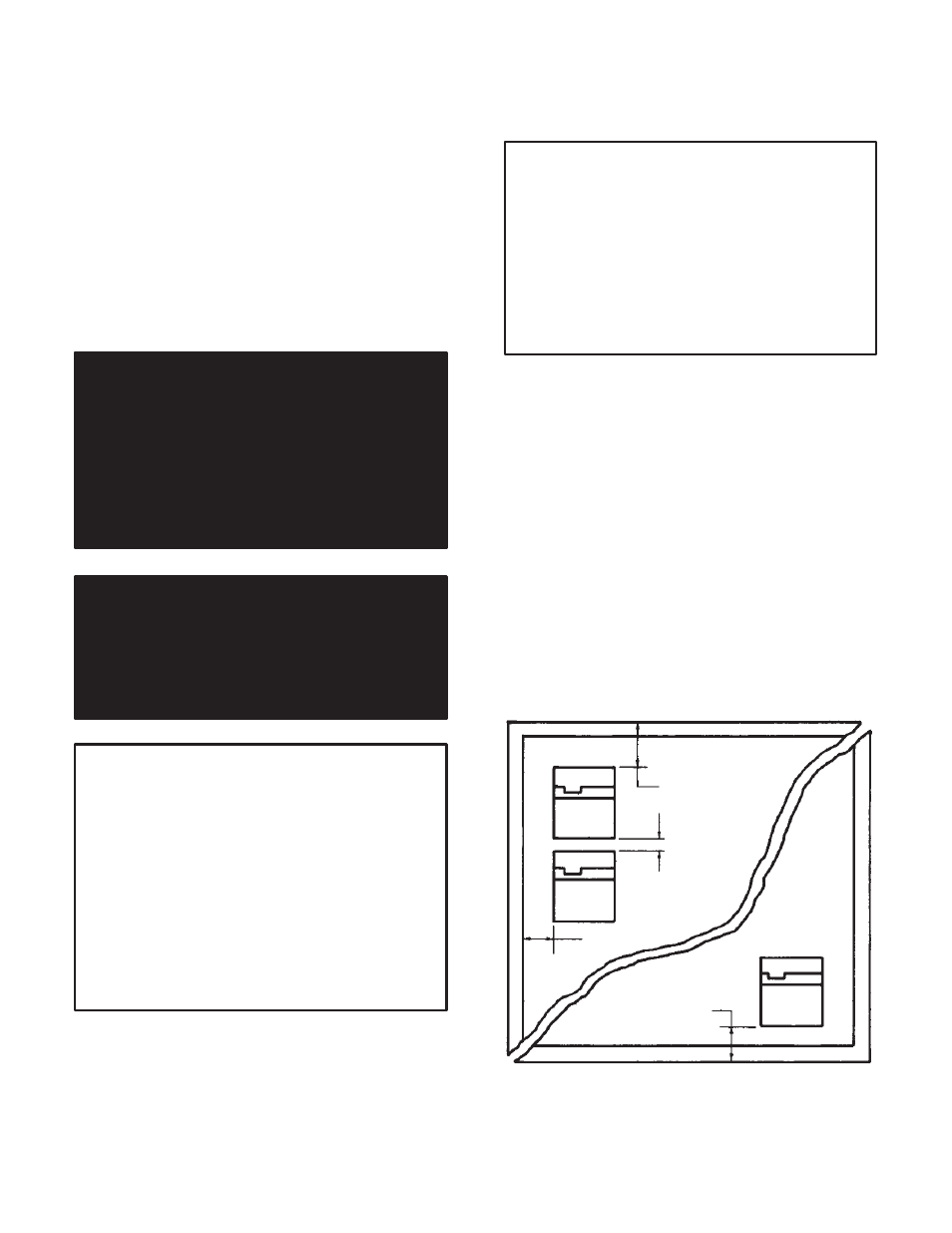
Guideline 2 - It is necessary to leave at least a 4 inch
(102 mm) clearance between controllers including top,
bottom and side. This unobstructed area allows for
proper air circulation through the heat sink. Do not
place the controller directly in a corner. Leave at least 8
inches (200 mm) from the top or 6 inches (150 mm) from
the bottom ofthe enclosure. (Refer to Figure 3.1.) Heat
builds up at the cabinet's top and may exceed the perĆ
missible inside ambient temperature upper limit. At the
cabinet's bottom, the unit must be high enough to allow
air to flow upwards.
8 in. (200 mm)
4 in. (102 mm)
4 in.
(102 mm)
6 in. (150 mm)
Figure 3.1 - Enclosure Mounting Minimum
Distances