Rockwell Automation FlexPak Plus NRG DC Drive User Manual
Page 13
12
WARNING
IN THE OPTIONAL BASIC DRIVE, THE USER
MUST INSTALL AN M CONTACTOR THAT HAS
A 115 VAC COIL WITH A MAXIMUM CURRENT
DRAW OF 440 MILLIAMPS. THE CONTACTOR
ADAPTER KIT MUST BE INSTALLED WITH THE
USER'S M CONTACTOR. (REFER TO DĆ3955)
PERSONAL INJURY MAY OCCUR IF THIS IS
NOT INSTALLED.
All interconnecting wire should primarily be sized and
installed in conformance with N.E.C., C.E.C. or local
codes. Refer to the controller and motor nameplates for
electrical data. Note that long cable runs may require
that a larger gauge be used to avoid excessive voltage
drop. Use of stranded wire, up to 19 strand, is also recĆ
ommended. Wire according to Figure 3.4.
After wiring, examine all terminals to determine that conĆ
nections are correctly made at both ends. Confirm wire
identification. Examine the firmness of the connections.
For applications using the 230V, 3Ć10 HPFlexPak Plus,
wires to the motor armature (A1 and A2) must be lugged
with the provided lugs, or equivalent, before connection
to the appropriate relay terminals.
WARNING
DO NOT ALLOW CONDUCTORS TO GROUND
ON THE CHASSIS. CHECK INTEGRITY OF ALL
WIRE INSULATION BEFORE DRAWING. REĆ
MOVE ONLY ENOUGH INSULATION TO MAKE A
FIRM TERMINAL CONNECTION. PERSONAL
INJURY COULD RESULT IF A BARE WIRE
TOUCHES THE CHASSIS.
3.4 Isolation Transformers
- Although an autoĆ
transformer may be required because of aĆc line voltage
levels, it is unable to provide a number of benefits stanĆ
dard with an isolation transformer.
The general requirements for an isolation transformer
are:
D Three phase
D 3 to 8% impedance
D Nonregulated
D Sinusoidal output
D 50/60 Hz, as required
D 150% overload for 1 minute (max.)
Refer also to Table 2.D for specific information on transĆ
former sizing requirements. In the Transformer" colĆ
umn at the right, maximum kVA and rated kVA figures
are listed in relation to specific dĆc motor hp/ VAC ratĆ
ings.
Reliance Electric offers a number of isolation transformĆ
ers suitable for use with the FlexPak Plus controller.
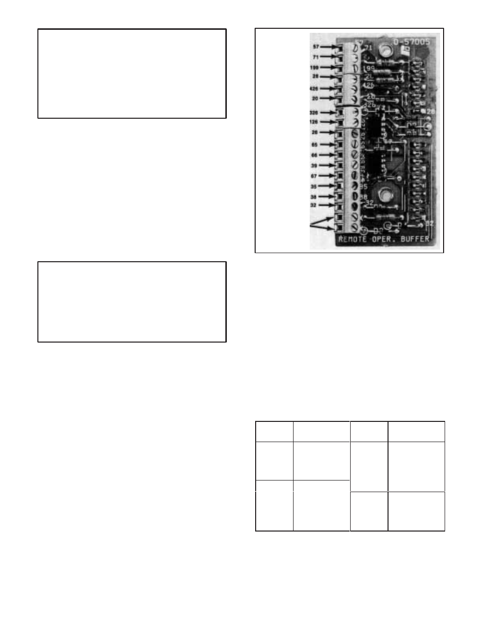
USER
CONVENIENCE,
BLANK
TERMINALS
Figure 3.5 - Remote Operators Buffer Terminal
Markings
3.5 HP/Current Jumper
- It is necessary to inĆ
spect the Current Scaling/Horsepower Jumper on the
Regulator Module to be sure that it is connected correctĆ
ly for a specific drive motor.
Step 1 - On the drive motor, locate the nameplate. Note
the fullĆload current.
Step 2 - Or, if current is not shown on the nameplate,
refer to Table 3.A. Relate the columns in the table with
known motor data. Read across to the right column
marked Motor Current." This figure indicates the propĆ
er jumper connection to make on the Module where a
corresponding number is etched.
Table 3.A - Horsepower Calibration
230 VAC
HP
Motor Current
Pin Connection
460 VAC
HP
Motor Current
Pin Connection
3
5
7.5
13
19
27
3
5
7.5
10
5.7
10
13
19
➀
10
36
15
27
15
20
54
72
20
➀
25
30
40
36
45
54
72
➀
High HPunits cannot be directly scaled to the lower HPunits, above
line, due to current transformers ratios used in feedback loop