Rockwell Automation FlexPak Plus NRG DC Drive User Manual
Page 17
16
DANGER
IF CIRCUIT BREAKER HAS TRIPPED OR FUSES
HAVE CLEARED THE FIELD SUPPLY, ITS WIRĆ
ING MUST BE INSPECTED FORDAMAGE.
REAPPLYING POWER TO THE DRIVE, THE
FIELD VOLTAGE MUST BE REĆCHECKED FOR
PROPER VOLTAGE AT MOTOR TERMINALS F1,
F2. IF THIS VOLTAGE IS BELOW 90% OF THE
FIELD VOLTAGE SPECIFIED ON THE MOTOR
NAMEPLATE, THE DRIVE MUST NOT BE
STARTED UNTIL PROPER VOLTAGE IS OBĆ
TAINED. FAILURE TO FOLLOW THIS PROCEĆ
DURE COULD RESULT IN OVERSPEEDING THE
MOTORAND/ORTHE MACHINERY COUPLED
TO THE MOTORSHAFT AND POSSIBLE FATAL
INJURY.
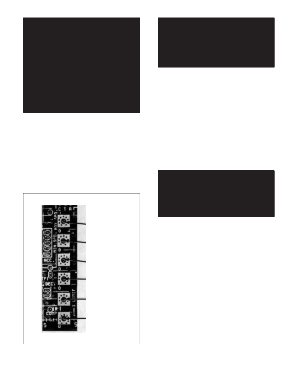
4.3.1 Regulator Module Pots - The Regulator Module
has six adjustable potentiometers mounted on it. (Refer
to Figure 4.1.) They control the following functions:
D Maximum speed (full CCW: 50 Ć70% speed)
D Minimum speed (full CCW: Drive Min. Speed 5%)
D Acceleration rate (full CCW)
D Deceleration rate (full CCW)
D Current limit (factoryĆset at 150%)
D IR comp (full CCW)
The potentiometers are factory preset for the safest or
most conservative operation.
MAX SPEED
MIN SPEED
ACC RATE
DECL RATE
CURRENT LIMIT
IRCOMP
Figure 4.1 - Regulator Module Potentiometers
DANGER
USE ONLY ON HAND TO HOLD THE SCREWĆ
DRIVER. KEEP YOUROTHERHAND BEHIND
YOU. DO NOT USE YOUROTHERHAND TO
BRACE YOURSELF AGAINST THE CONTROLĆ
LER, PANEL OR ENCLOSURE. PERSONAL INĆ
JURY COULD RESULT IF YOU ACCIDENTALLY
TOUCH A COMPONENT AT LINE VOLTAGE.
4.3.2 Maximum Speed (Voltage) - The Maximum
Speed Potentiometer on the Regulator Module has
been factory preset for 70% of a typical motor base
speed of about 1750 rpm. By means of adjustment, the
maximum speed may be raised to suit the application.
The result is the highest speed that can be set by the opĆ
erator on the SPEED dial. The control range is 70 to
100% of rated speed.
The method for determining if the motor and driven
equipment are operating at an acceptable maximum
speed for the application is measure speed with a
tachometer.
Locate the Maximum Speed Potentiometer on the RegĆ
ulator Module. (Refer to Figure 4.1.) The letters MAX
SPD are printed on the Module. Note that CW rotation
represents an increase in speed. CCW represents a
decrease.
DANGER
WHEN PERFORMING THIS ADJUSTMENT PROĆ
CEDURE, DO NOT ALLOW THE DRIVE MOTOR
TO EXCEED ITS RATED MAXIMUM SPEED, AS
LISTED ON THE NAMEPLATE. EQUIPMENT
DAMAGE AND SERIOUS PERSONAL INJURY
COULD RESULT.
On the Operator Station, increase the SPEED dial slowĆ
ly in the direction of 10, which is 100% of full travel. If, as
the SPEED dial is turned toward the 10 setting, the
speed exceeds the maximum acceptable speed, imĆ
mediately decrease the maximum speed on the
SPEED dial. Use a small insulated slot screwdriver.
In some cases, to avoid exceeding the maximum operĆ
ating speed, it may be necessary to turn the Maximum
Speed Potentiometer completely CCW before turning
the SPEED dial completely CW.
If the 10 setting on the SPEED dial is lower than the deĆ
sired speed, increase the setting on the Maximum
Speed Potentiometer to the necessary speed. To inĆ
crease the maximum speed, turn the potentiometer CW.
NOTE: A further adjustment may be needed but It
should be performed after completing Paragraph
4.3.3. Note that the maximum and minimum speed
adjustments are interactive; a change in one affects
the other.