Rockwell Automation FlexPak Plus NRG DC Drive User Manual
Page 10
9
Guideline 3 - Regardless of the above placement
guidelines, the user is responsible for providing ambiĆ
ent temperatures that meet the controllers specificaĆ
tions of 0
°
to 55
°
C (32
°
to 131
°
F). This must be given
careful consideration especially to units located near
the very top of the supplied enclosure. Relative humidity
must be kept between 5 and 95% without condensaĆ
tion.
Guideline 4 - Due to the UĆshaped panel design of the
FlexPak Plus, the controller must be mounted in the verĆ
tical position to allow for proper cooling.
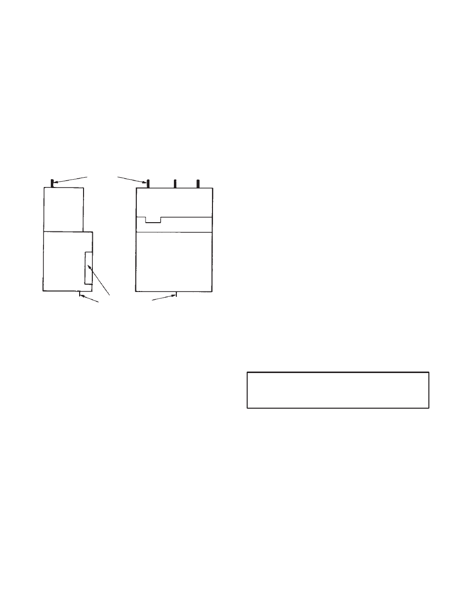
The controller is also designed to allow for power wiring
to enter from the top and for control and signal wiring to
be routed in thru the openings in the sides of the controlĆ
ler or from the bottom. (Refer to Figure 3.2.)
POWER
WIRING
CONTROL AND
SIGNAL WIRING
LEFT SIDE VIEW
FRONT VIEW
Figure 3.2 - Mounting and Wiring Orientations
Guideline 5 - Do not route the tachometer feedback
signal cable, if used, with aĆc or dĆc control or power wirĆ
ing. Also use the specified wire for this function..
Guideline 6 - Although autoĆtransformers may step up
and step down aĆc power supply voltage, they do not
isolate the driven system from the aĆc line. Users should
consider using an isolation transformer if the applicaĆ
tion conditions warrant it.
If an isolation or autoĆtransformer is used ahead of the
controller, the disconnect switch should be placed on
the aĆc power line between the power source and the
transformer primary. Again, use a f used disconnect
switch. (Do not use a circuit breaker type switch beĆ
cause of the high inrush of transformer equipment.).
An isolation transformer is not necessary unless the apĆ
plication conditions require one. However, its use proĆ
vides distinct advantages. With an isolation transformĆ
er:
D Personal injury is guarded against should accidental
contact be made with an electrical conductor from
the drive.
D AĆc power line disturbances, or transients, are
minimized by an isolation transformer, thereby reĆ
ducing or eliminating damage to other solidĆstate
equipment powerĆconversion components in the
controller and other userĆequipment on the same ac
line.
D The transformer provides electrical isolation beĆ
tween the aĆc power lines and the drive motor.
Damaging currents may be eliminated in instances
where a dĆc output accidentally becomes grounded
in a unit where the aĆc electrical system is grounded.
For detailed information, refer to Paragraph 3.4.
Guideline 7 - The National Electrical Code requires
that a threeĆpole, fused disconnect switch be installed
on the incoming aĆc line ahead of the controller to proĆ
vide branch circuit protection. The fuse should be Class
K5.
It is recommended that the disconnect switch be placed
within easy reach of operating and maintenance perĆ
sonnel. Do not place it inside a surrounding enclosure
since cabinet doors may be locked. (Consult your local
codes.)
Guideline 8 - It is necessary to connect the GND
(Green/ground) wire of the threeĆconductor incoming
aĆc line to the terminal provided on the Chassis. Ring
type connectors are recommended. The user must be
sure that the ground wire is connected to the plant
ground at the source.
The motor frame should also be grounded. In many
cases it is adequate to use a screw in the conduit box
near the motor.
Guideline 9 - A thermostat is used to guard against
motor overload protection, It is essential to properly
connect the motor thermostat to connections 34 and
132.
CAUTION: External overload devices must be conĆ
nected between terminals 32, 33, 34 and 132. The
drive will not start without them.
Refer to Figure 3.4 where a typical Operator's Station
schematic is shown.
Guideline 10 - When planning signal or control wire
runs, follow these practices:
D Conduits should be steel.
D If these conduits cross 460 VAC conductors, make
sure the cross is at 90
°
.
D Do not route signal wires through junctions or
terminal boxes that contain nonĆsignal aĆc or dĆc
(115/230/460V) wires.