Using logic command/ status, 3 using logic command/status – Rockwell Automation RECOMM-CNET ControlNet Communications Module User Manual
Page 54
6-4
ControlNet Communications Module
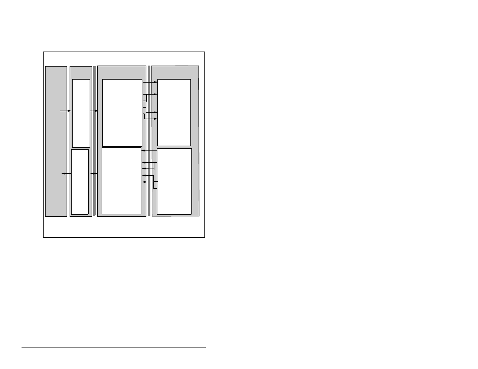
Figure 6.2 illustrates an example of an I/O image that does not use
all of the I/O data. Only the Logic Command/Reference and
Datalink B are enabled. In this example, the Reference is a 32-bit
word, and Datalinks are 16-bit words.
6.3
Using Logic Command/Status
When enabled, the Logic Command/Status word is always word 0 in
the I/O image. The Logic Command is a 16-bit word of control
produced by the scanner and consumed by the module. The Logic
Status is a 16-bit word of status produced by the module and
consumed by the scanner.
This manual contains the bit definitions for compatible products
available at the time of publication in Appendix D, Logic Command/
Status Words. For other products, refer to their documentation.
Figure 6.2 – Sample I/O Image with Only Logic/Reference and Datalink B
Enabled
Controller
Scanner
Module
SP600 Drive
ControlNet
DPI
Output
Image
(Write)
Input
Image
(Read)
0 Logic Status
1 Pad Word
2 Feedback (LSW)
3 Feedback (MSW)
4 Datalink Out B1
5 Datalink Out B2
0 Logic Command
1 Pad Word
2 Reference (LSW)
3 Reference (MSW)
4 Datalink In B1
5 Datalink In B2
Word and I/O
Logic Command
Reference
Data In A1
Data In A2
Data In B1
Data In B2
Data In C1
Data In C2
Data In D1
Data In D2
Logic Status
Feedback
Data Out A1
Data Out A2
Data Out B1
Data Out B2
Data Out C1
Data Out C2
Data Out D1
Data Out D2
LSW = Least Signicant Word (Bits 15 - 0)
MSW = Most Significant Word (Bits 31 - 16)