Rockwell Automation SP500 AC Drive Installation and Operation Manual User Manual
Page 97
Troubleshooting Reference
9-7
9.4
Checking the Drive’s Power Module Circuitry with the
Power Off
Use the following procedure to check the drive’s Power Module circuitry. Note that this
test is performed with the power off.
Step 1. Turn off and lock out input power. Wait five minutes.
Step 2. Remove the drive’s cover.
Step 3. Verify that there is no voltage at the drive’s input power terminals.
Step 4. Check the DC bus voltage with a voltmeter as described in section 9.1 to
ensure that the DC bus capacitors are discharged.
Step 5. Disconnect the motor from the drive.
Step 6. Check all AC line and DC bus fuses.
Step 7. If a fuse is open, use a multimeter to check the input diodes and output
IGBTs. See tables 9.2 and 9.3.
Step 8. Reconnect the motor to the drive.
Step 9. Reattach the drive’s cover.
Step 10. Reapply input power.
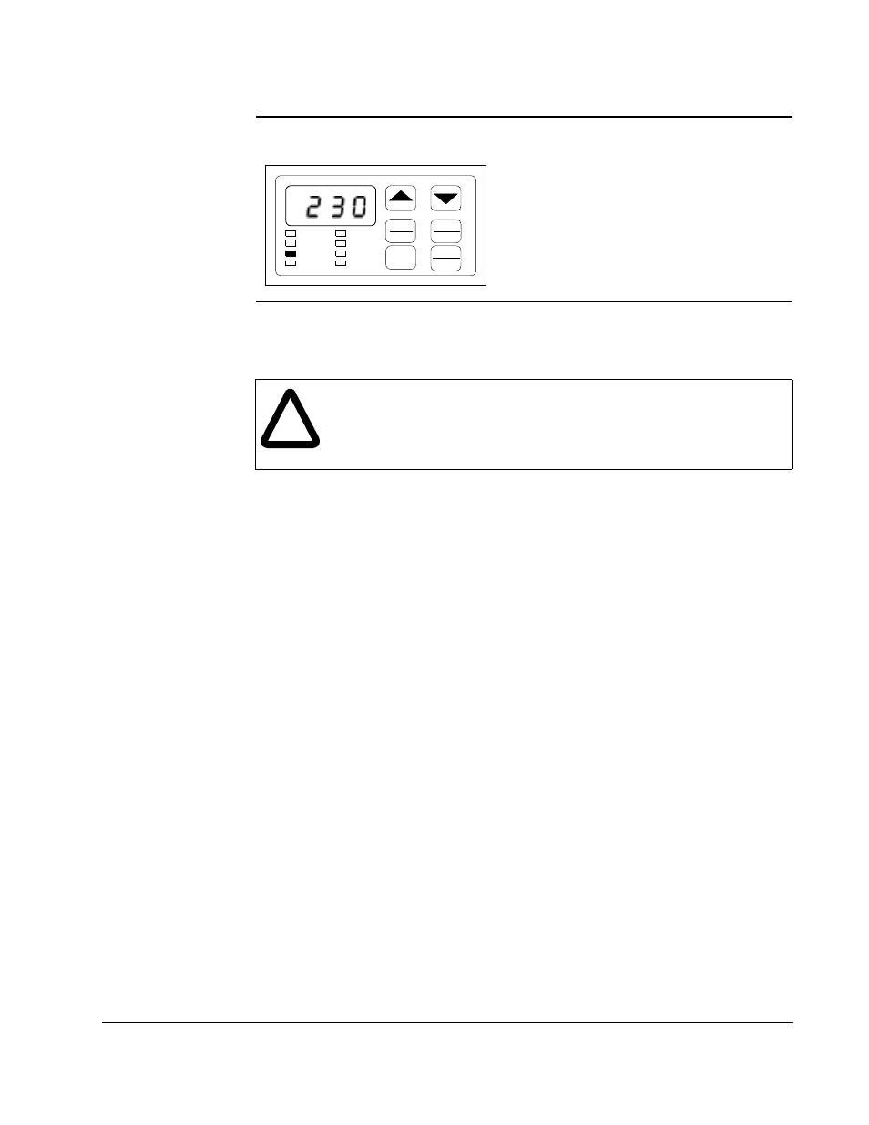
Step 5. Press the STOP/RESET key to clear the log.
The display will return to the active monitor
display.
Mode
Enter
START
Forward
Reverse
STOP
RESET
RPM
%Load
Volts
Remote
RUN
Program
Forward
Reverse
!
ATTENTION: DC bus capacitors retain hazardous voltages after input
power has been disconnected. After disconnecting input power, wait five
(5) minutes for the DC bus capacitors to discharge and then check the
voltage with a voltmeter to ensure the DC bus capacitors are discharged
before touching any internal components.