Rockwell Automation SP500 AC Drive Installation and Operation Manual User Manual
Page 100
A-2
SP500 AC Drive Installation and Operation Manual Version 3.1
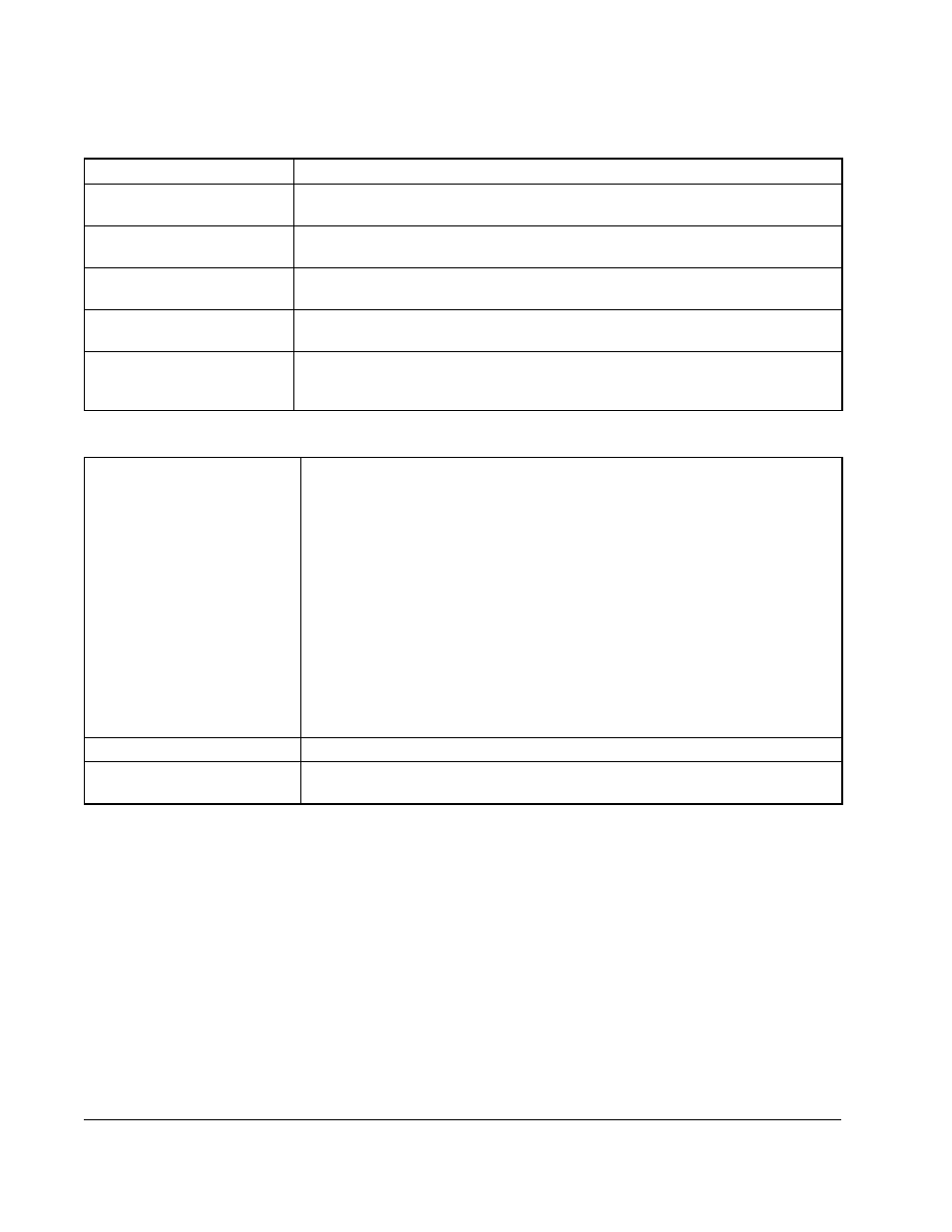
Table A.4 – Drive Inputs
Analog Speed Reference
0 to 10 VDC or 0 to 20 mA
Start
Edge-sensitive signal that must see an open-to-closed contact transition. This
transition may be a momentary or fixed closure.
Stop
An open contact that must be closed when the drive is running. The drive will
remain off as long as the contact is open.
IET Reset
Edge-sensitive signal that must see an open-to-closed contact transition. This
transition may be a momentary or fixed closure.
Forward/Reverse
An open contact to assert the forward direction and a closed contact to assert
the reverse direction.
Function Loss
An open contact that must be closed when the drive is running. When the
contact is open, the drive turns off. The drive will remain off as long as the
contact is open.
Table A.5 – Drive Outputs
Analog Output
(0-10 VDC scaled signal)
The scaled signal is selected through parameter F-29 and can be one of the
following:
•
Output Voltage:
0 to 115 VAC (M/N 1SU1xxxx drives)
0 to 253 VAC (M/N 1SU2xxxx drives)
0 to 506 VAC (M/N 1SU4xxxx drives)
0 to 632 VAC (M/N 1SU5xxxx drives)
•
% Load (Amps): 0 to 200% (Percentage of output amps based on the drive
nameplate.)
•
RPM/Engineering Unit: Minimum to maximum RPM or minimum to
maximum of any engineering unit (See parameter
F-08)
•
% Selected Speed Reference: 0 to 100% (Percentage of the selected
reference signal range.)
Snubber Resistor Braking
Snubber resistor control signal used by an optional snubber resistor.
Output Status Relay
115 VAC/24 VDC, 0.5 Amp, relay output (One Form A and one Form B
contact wired with a single common.)