3 led descriptions – Rockwell Automation SP500 AC Drive Installation and Operation Manual User Manual
Page 67
Keypad and Display Operation
7-3
7.3
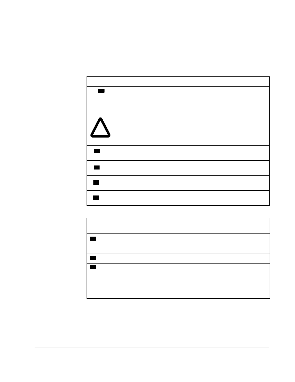
LED Descriptions
The keypad area contains eight LEDs that indicate either drive status or which drive
output value is displayed in monitor mode. Tables 7.2 and 7.3 describe the drive status
LEDs and monitor mode LEDs, respectively.
Table 7.2 – Drive Status LED Descriptions
LED
State
Description
On
Off
The drive is generating an output voltage and
frequency.
The drive is not generating an output voltage and
frequency.
ATTENTION:The RUN LED must not be used as an indication that
there is no line voltage present in the drive. Verify there is no voltage
present at the DC bus terminals (+) and (–) before servicing the drive.
Failure to observe this precaution could result in severe bodily injury
or loss of life.
On
Off
The keypad and display are in program mode.
The keypad and display are in monitor mode.
On
Off
The requested motor rotation direction is forward.
The requested motor rotation direction is not forward.
On
Off
The requested motor rotation direction is reverse.
The requested motor rotation direction is not reverse.
On
Off
The drive is being controlled from the terminal strip.
The drive is being controlled from the keypad.
Table 7.3 – Monitor Mode LED Descriptions
LED
Corresponding Display When LED is On
(Actual Value)
Motor speed in RPM or in a user-specified engineering
unit. (Refer to the F-08 parameter description for more
information).
Percentage of drive full load amps rating.
Drive output voltage to the motor.
All LEDs (RPM, Volts,
%Load)
Value of the active speed reference signal as 0 to 100% of
the total scaled reference range. F-13 must be set to ON
to display this value. (Refer to the F-13 parameter
description for more information).
!
Volts
RPM/Engineering
Unit
%Load
Run
Reverse
Remote
Program
Forward