2 troubleshooting the drive using fault codes – Rockwell Automation SP500 AC Drive Installation and Operation Manual User Manual
Page 93
Troubleshooting Reference
9-3
9.2
Troubleshooting the Drive Using Fault Codes
Table 9.1 defines the fault codes for user-correctable faults, lists possible causes, and
suggests actions to take to correct the problem. All other faults require replacement
of the drive.
If a fault occurs, do the following:
Step 1. Try to clear the fault first by pressing the STOP/RESET key or asserting the
IET reset input (remote operation). If the fault reoccurs, continue with step 2.
Step 2. Refer to table 9.1 to identify the fault code and the possible causes.
Step 3. Perform the suggested corrective action(s).
Step 4. Clear the fault by pressing the STOP/RESET key or asserting the IET reset
input.
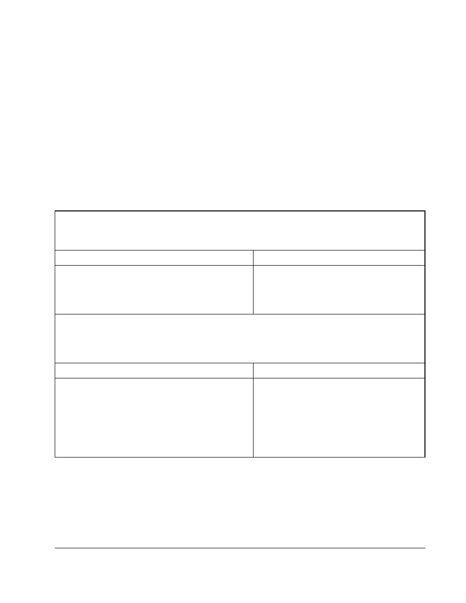
Table 9.1 – Drive Faults and Corrective Actions
The function loss input signal has been asserted (terminals 10 and 11).
Possible Cause
Corrective Action
The external equipment connection to the function loss
terminals has failed or is giving repeated stop requests.
Check the external equipment wired to the
remote function loss terminals (10 and 11).
Refer to chapter5.
Check the function loss input connections.
The DC bus is charged above the electronic trip threshold. Note that the fault will not clear until the bus falls
below the high bus level.
Possible Cause
Corrective Action
The deceleration rate setting in F-02 is too fast.
Decrease the deceleration rate in F-02. Refer to
chapter 8 for the F-02 parameter description.
Install the optional snubber resistor braking kit.
The drive was started into a forward-running load that
has a high inertia.
Install the optional snubber resistor braking kit.
High input line.
Verify that the AC input is within specification.
Install an isolation transformer if required.
FL
= FUNCTION LOSS
HU
= HIGH BUS VOLTAGE