2 typical multiple drive connection examples – Rockwell Automation MD65 User Manual Version 2.0 User Manual
Page 43
Installing Control Wiring
6-9
6.4.2 Typical Multiple Drive Connection Examples
Analog Output
A065 (Analog Out Sel)
determines analog
output type and drive
conditions.
0-10V,
1k ohm minimum
0-20mA/4-20mA,
525 ohm maximum
A065 (Analog Out Sel) = 0 through 14
The Analog Output Select DIP Switch must be set to match the analog output
signal mode set in A065 (Analog Out Sel).
Input/Output
Connection Example
14
16
Common
+
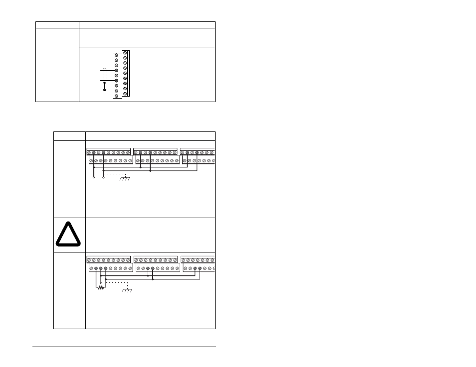
Table 6.4 – Typical Multiple Drive Connection Examples
Input
Connection Example
Multiple Digital
Input
Connections
When connecting a single input such as Run, Stop, Reverse or Preset
Speeds to multiple drives, it is important to connect I/O Terminal 04
common together for all drives. If they are to be tied into another common
(such as earth ground or separate apparatus ground) only one point of
the daisy chain of I/O Terminal 04 should be connected.
!
ATTENTION: I/O Common terminals should not be
tied together when using SNK (Internal Supply)
mode. In SNK mode, if power is removed from one
drive, inadvertent operation of other drives that
share the same I/O Common connection may occur.
Multiple Analog
Connections
When connecting a single potentiometer to multiple drives it is important
to connect I/O Terminal 14 common together for all drives. I/O Terminal
14 common and I/O Terminal 13 (potentiometer wiper) should be daisy-
chained to each drive. All drives must be powered up for the analog signal
to be read correctly.
Customer Inputs
Optional Ground Connection
04
02
04
02
04
02
Remote Potentiometer
Optional Ground Connection
12
13 14
13 14
13 14