Rockwell Automation MD65 User Manual Version 2.0 User Manual
Page 39
Installing Control Wiring
6-5
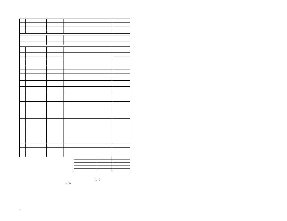
Table 6.3 – Control Terminal Definitions and Related Parameters
No.
Signal
Default
Description
Parameter
R1
Relay N.O.
Fault
Normally open contact for output relay.
A055
R2
Relay Common
–
Common for output relay.
R3
Relay N.C.
Fault
Normally closed contact for output relay.
A055
Analog Output Select DIP
Switch
0-10 V
Sets analog output to either voltage or current. Setting must match Analog
Out Sel (A065).
Sink/Source DIP Switch
Source (SRC)
Inputs can be wired as Sink (SNK) or Source (SRC) via DIP Switch setting.
01
Stop
1, 4
Coast
The factory-installed jumper or a normally closed input
must be present for the drive to start.
P036
1, 4
02
Start/Run FWD
Not Active
Command comes from the integral keypad by default. To
disable reverse operation, see Reverse Disable (A095).
P036, P037
03
Dir/Run REV
Not Active
P036, P037, A095
04
Digital Common
–
For digital inputs. Electronically isolated with digital
inputs from analog I/O and opto outputs.
05
Digital Input 1
Preset Freq
Program with Digital In1 Sel (A051).
A051
06
Digital Input 2
Preset Freq
Program with Digital In2 Sel (A052).
A052
07
Digital Input 3
Local
Program with Digital In3 Sel (A053).
A053
08
Digital Input 4
Jog Forward
Program with Digital In4 Sel (A054).
A054
09
Opto Common
-
For opto-coupled outputs. Electronically isolated with
opto outputs from analog I/O and digital inputs.
11
+24V DC
–
Referenced to Digital Common.Drive supplied power for
digital inputs. Maximum output current is 100 mA.
12
+10V DC
–
Referenced to Analog Common. Drive supplied power
for digital 0-10 V external potentiometer. Maximum
output current is 15 mA.
P038
13
+/-10V In
5
Not Active
For external 0-10 V (unipolar) or +/-10 V (bipolar) input
supply (input impedance = 100 k Ohm) or potentiometer
wiper.
P038, A051-A054,
A123, A132
14
Analog Common
–
For 0-10 V In or 4-20 mA In. Electronically isolated with
analog inputs and outputs from digital I/O and opto
outputs.
15
4-20mA In
5
Not Active
For external 4-20 mA input supply
(input impedance = 250 Ohm).
P038, A051-A054,
A132
16
Analog Output
OutFreq 1-10
The default analog output is 0-10 V. To convert to a
current value, change the Analog Output Select DIP
Switch to 0-20 mA. Program with Analog Out Sel (A065).
Max analog value can be scaled with Analog Out High
(A066).
Maximum Load: 4-20 mA = 525 ohm (10.5 V)
0-10 V = 1k ohm (10 mA)
A065, A066
17
Opto Output 1
MotorRunning
Program with A058 (Opto Out1 Sel)
A058, A059, A064
18
Opto Output 2
At Frequency
Program with A061 (Opto Out2 Sel)
A061, A062, A064
19
RS485 Shield
-
Terminal should be connected to safety ground- PE
when using the RS485 communications port.
1
Important: I/O Terminal 01 is always a coast-to-
stop input except when Start Source (P036) is set
to “3-Wire Control.” In three-wire control, I/O
Terminal 01 is controlled by Stop Mode (P037). All
other stop sources are controlled by Stop Mode
(P037).
P036 (Start Source)
Stop
I/O Terminal 01 Stop
Keypad
Per P037
Coast
3-Wire
Per P037
Per P037
4
2-Wire
Per P037
Coast
RS485 Port
Per P037
Coast
Important: The drive is shipped with a jumper installed between I/O Terminals 01 and 11. Remove this
jumper when using I/O Terminal 01 as a stop or enable input.
2
Two-wire control shown. For three-wire control, use a momentary input
on I/O Terminal 02 to
command a start. Use a maintained input
for I/O Terminal 03 to change direction.
3
When using an opto output with an inductive load such as a relay, install recovery diode parallel to the
relay as shown to prevent damage to the output.
4
When the ENBL enable jumper is removed, I/O Terminal 01 will always act as a hardware enable, causing
a coast to stop without software interpretation.
5
0-10 V In and 4-20 mA In are distinct input channels and may be connected simultaneously. Inputs may
be used independently for speed control or jointly when operating in PID mode.