Rockwell Automation RECOMM-PBUS PROFIBUS Communications Module User Manual
Page 54
6-2
PROFIBUS Communications Module
The I/O image table will vary based on the following:
•
Size (either 16-bit or 32-bit) of the Reference/Feedback word and
Datalink words used by the drive.
•
Configuration of parameter 11 (DPI I/O Config). If not all I/O is
enabled, the image table is truncated. The image table always
uses consecutive words starting at word 0.
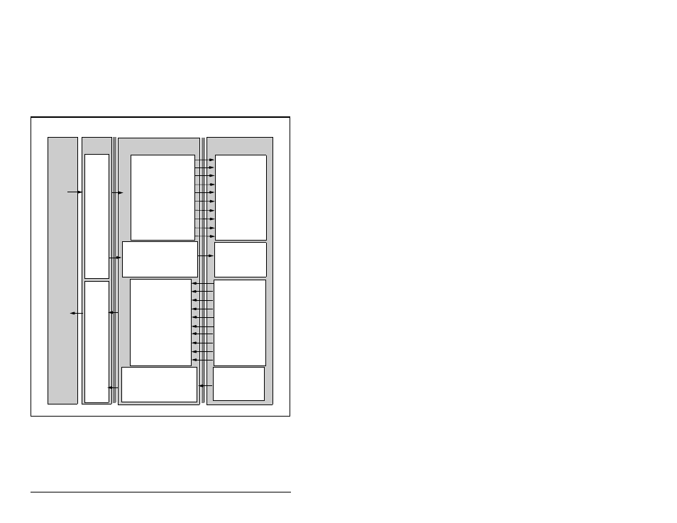
Figure 6.1 illustrates an example of an I/O image with 16-bit words.
Figure 6.1 – Sample I/O Image with All I/O Enabled
Controller
Scanner
Module
SP600 Drive
PROFIBUS
DPI
Output
Image
(Write)
Input
Image
(Read)
0 Logic Status
1 Feedback
2 Datalink Out A1
3 Datalink Out A2
4 Datalink Out B1
5 Datalink Out B2
6 Datalink Out C1
7 Datalink Out C2
8 Datalink Out D1
9 Datalink Out D2
0 Logic Command
1 Reference
2 Datalink In A1
3 Datalink In A2
4 Datalink In B1
5 Datalink In B2
6 Datalink In C1
7 Datalink In C2
8 Datalink In D1
9 Datalink In D2
Logic Status
Feedback
Data Out A1
Data Out A2
Data Out B1
Data Out B2
Data Out C1
Data Out C2
Data Out D1
Data Out D2
Word and I/O
Message
Handler
Message
Handler
10 Parameter Access Word 1
11 Parameter Access Word 2
12 Parameter Access Word 3
13 Parameter Access Word 4
10 Parameter Access Word 1
11 Parameter Access Word 2
12 Parameter Access Word 3
13 Parameter Access Word 4
Logic Command
Reference
Data In A1
Data In A2
Data In B1
Data In B2
Data In C1
Data In C2
Data In D1
Data In D2