Applying ferrite sleeves, Splicing motor power cables – Rockwell Automation System Design for the Control of Electrical Noise User Manual
Page 75
Publication GMC-RM001A-EN-P — July 2001
Motor Wiring
8-3
Applying Ferrite Sleeves
A ferrite sleeve around the three power conductors as they leave the
drive will help to reduce common-mode noise current. Take all three
conductors two or three times through the core. If it runs hot reduce
the number of turns.
Note: Not all drives allow the use of a ferrite sleeve around power
conductors. Refer to your manual for specific applications.
Splicing Motor Power
Cables
Avoid splicing motor power cables when ever possible. Ideally, motor
power cables should run continuous between the drive and motor
terminals. The most common reason for splicing is to incorporate
high-flex cable for continuous flexing applications.
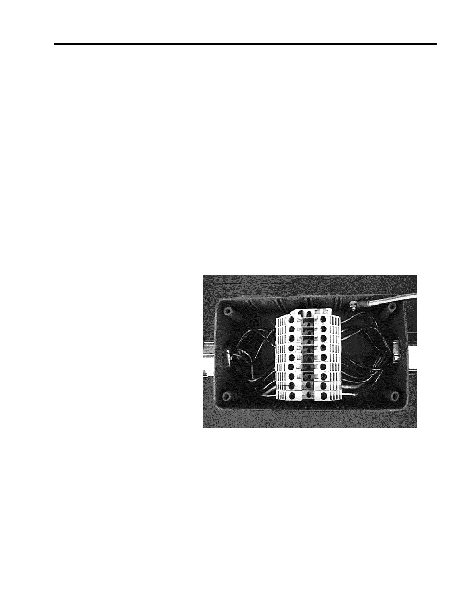
If necessary, the preferred method of splicing is to use a fully shielded
bulkhead connector. Splicing can also be accomplished using a
grounded and shielded junction box, as shown in the figure below.
Figure 8.3
Spliced cable using junction box
Observe the following guidelines when installing a junction box:
•
Shield drain wire must be spliced only to mating shield drain
wires and not grounded at the junction box.
•
Feedback shields must be passed through pin for pin.
•
Separate junction boxes for power and feedback are required.