Using a dynamic braking contactor, Attention – Rockwell Automation System Design for the Control of Electrical Noise User Manual
Page 115
Publication GMC-RM001A-EN-P — July 2001
Noise Control Supplement
A-13
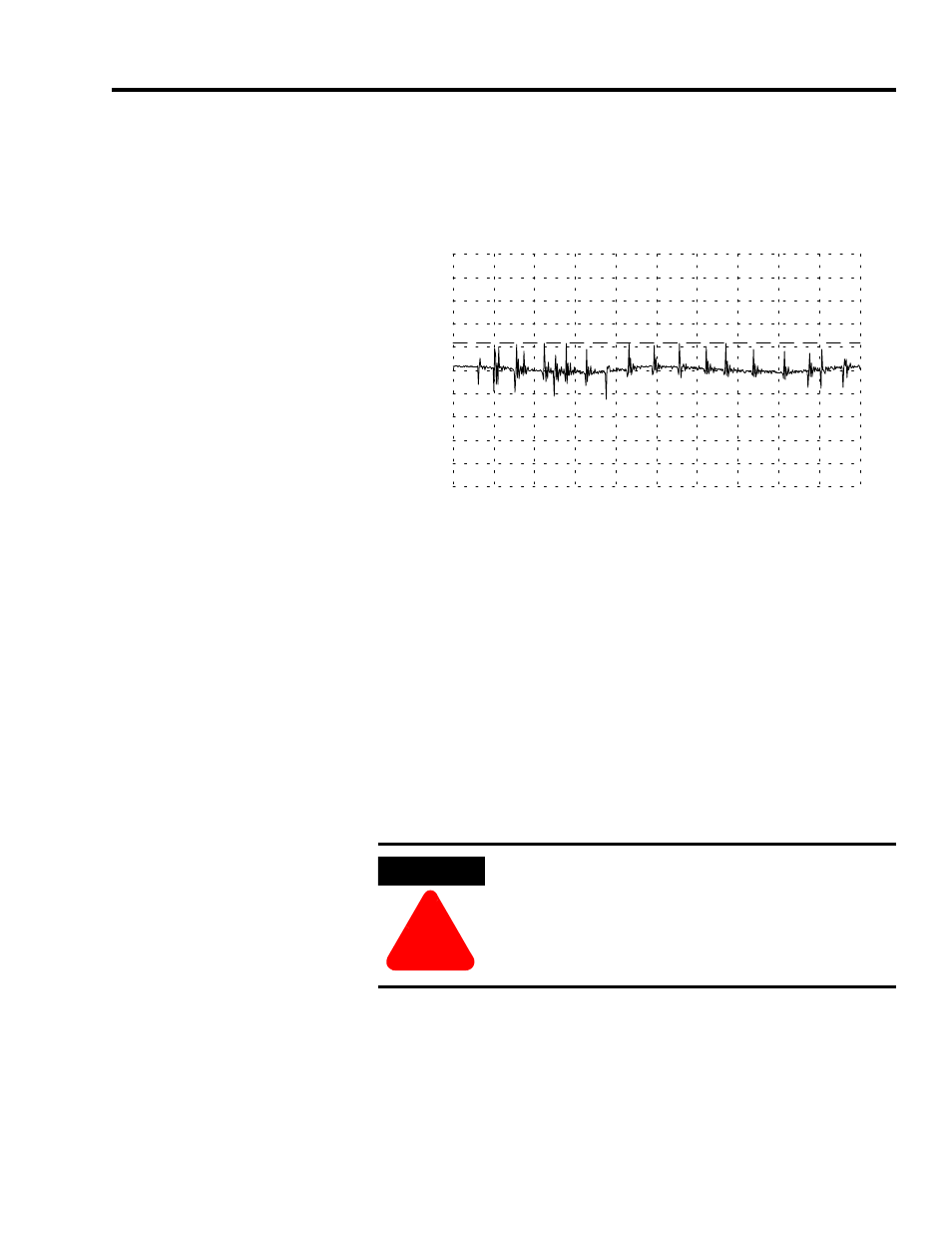
In Figure A.12 noise spikes greater than 2V, from an unsuppressed
inductive load are seen on the DC circuit of the second PSU.
Figure A.12
Noise spikes on +24V dc terminal of second PSU
Using a Dynamic Braking
Contactor
Dynamic braking (as shown in Figure A.13) requires the insertion of a
three-phase contactor between drive and motor and satisfies two
requirements.
•
Safety isolation where an operator must physically intervene in a
process. Usually combined with safety sensors such as a light
curtain.
•
Emergency braking in the event of power failure. This requires
three resistors connected across the motor windings by normally
closed contacts. The motor acts as a generator and the power is
dissipated by the resistors.
Note: Dynamic braking resistors are frequently confused with
dump-resistors which dissipate excess power from the DC bus
of a drive when a motor is regenerating.
µs
-10V
-8
-6
-4
-2
0
2
4
6
8
10V
2.3V pk
Victim Omron +24Vdc
DC floating
-1
0
1
2
3
4
5
6
7
8
9
ATTENTION
!
To avoid personal injury and/or damage to
equipment, the resistors must be installed. Opening
the circuit without resistors can result in very high
voltages due to motor inductance, prolonged arcing,
and eventually cause a fire in the contactor.