Noise example 1, Noise example 1 -2 – Rockwell Automation System Design for the Control of Electrical Noise User Manual
Page 20
Publication GMC-RM001A-EN-P — July 2001
2-2
High Frequency (HF) Bonding
Noise Example 1
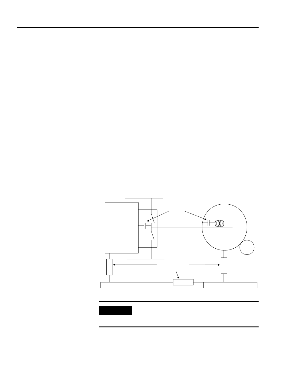
The transistors impose a 600V step change in the wire B (typically less
than 200nS). Stray capacitance A charges very rapidly causing a
current spike. This is the dominant noise source in PWM (Pulse Width
Modulated) drive systems.
The current circulates through stray capacitance C, bonding
impedance D, bonding impedance E, bonding impedance F, and back
to stray capacitance A. A voltage spike will appear between motor
frame and machine structure (Vd), between machine structure and the
panel (Ve) and between the panel and drive chassis (Vf).
The circuit of an encoder mounted on the motor will then have a
voltage spike of amplitude Vd + Ve relative to the panel and to any
input circuit on the panel, potentially a noise victim.
The noise voltages are proportional to the impedance of the bonds
(voltage = current x impedance). If these are reduced to zero, no
voltage will appear between encoder and panel.
Figure 2.1
Switching noise affecting encoder signal
+600V dc
DC common
Heatsink
(connected
to chassis)
Panel
Machine Structure
Windings
Motor
Drive
Stray
capacitance
Impedance due to
poor bonding
Transistor block
A
D
E
B
C
F
Encoder
IMPORTANT
The quality of bonding techniques applied during
installation directly affects the noise voltages
between system components.