Data/communications cables – Rockwell Automation System Design for the Control of Electrical Noise User Manual
Page 39
Publication GMC-RM001A-EN-P — July 2001
Segregating Sources and Victims
3-7
Data/Communications Cables
Data and communication cables that come from a remote structure
(refer to the chapter High Frequency (HF) Bonding) will carry noise
on their shields. Follow the guidelines listed below when installing
data or communication cables.
•
Follow the product manual recommendations for termination
resistors, minimum and maximum length, etc.
•
Carefully segregate data and communication cables from dirty and
especially very-dirty cables.
•
Ground shields to the panel at the point of entry when permitted.
Check your manual for the recommended procedure. Connecting
to the 360° shield is preferable to the use of pigtails. If pigtails
must be used, they should be kept short. Refer to the section
Grounding Cable Shields in Appendix A for more information on
grounding cable shields.
•
Refer to the chapter Filtering Noise for more information.
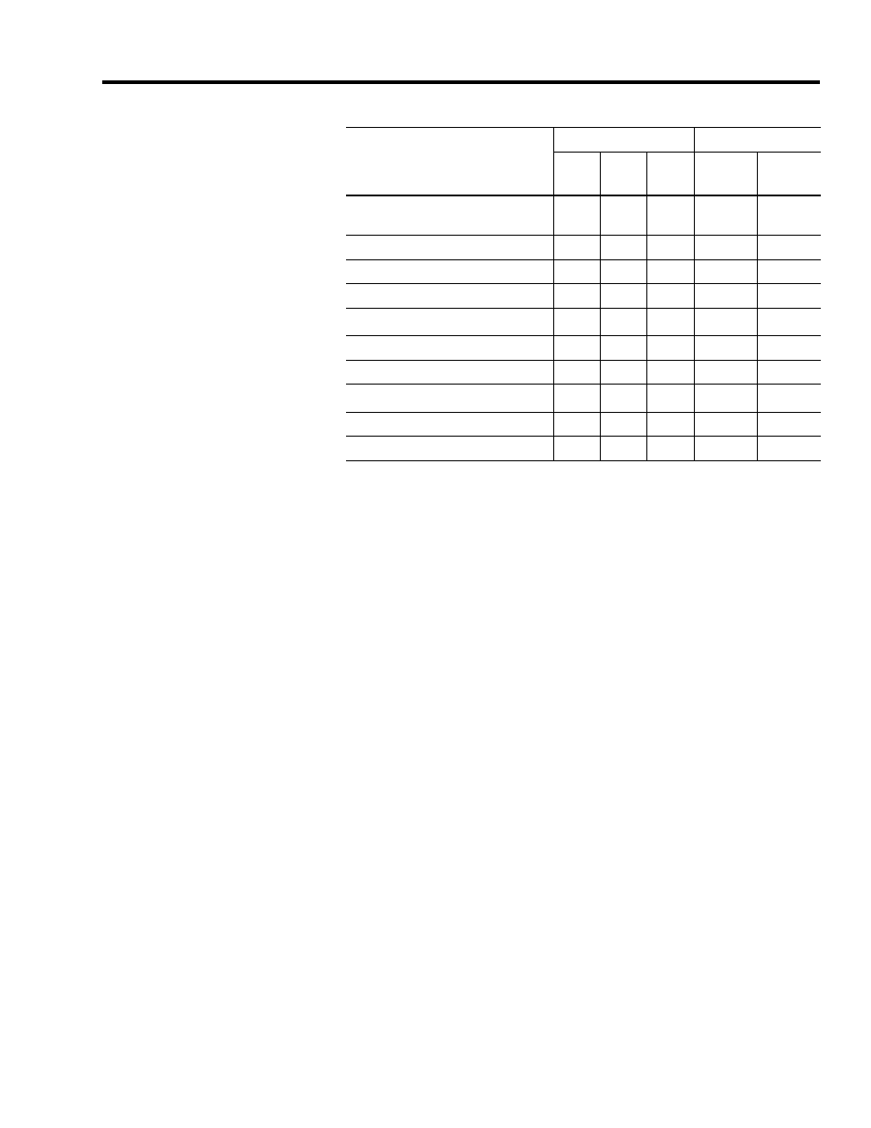
Proximity Switches (except
registration)
X
Photoelectric Cell
X
24V dc Relay
X
Transformer Indicator Lamp
X
Data/Communications
4
X
X
X
Encoder/Resolver
X
X
Logic circuit power
X
X
High Speed Registration inputs
5
X
X
PLC Analog I/O
X
X
PLC High Speed Counter input
X
X
1
An X in this column indicates a ferrite sleeve fitted to the wire is recommended.
2
An X in this column indicates a shielded cable is recommended.
3
Keep unshielded conductors as short as possible and separated from dirty and clean cables as far as possible.
4
Refer to the section Data/Communications Cables below for more information.
5
Refer to the chapter High Speed Registration Inputs for more information.
Note: Grounding power cable shields at entry to the cabinet is recommended.
Cable and Wire Category
Zone
Method
Very-
Dirty
Dirty
Clean
Ferrite
Sleeve
1
Shielded
Cable
2