Noise example 2, The ground plane principle, Noise example 2 -3 the ground plane principle -3 – Rockwell Automation System Design for the Control of Electrical Noise User Manual
Page 21
Publication GMC-RM001A-EN-P — July 2001
High Frequency (HF) Bonding
2-3
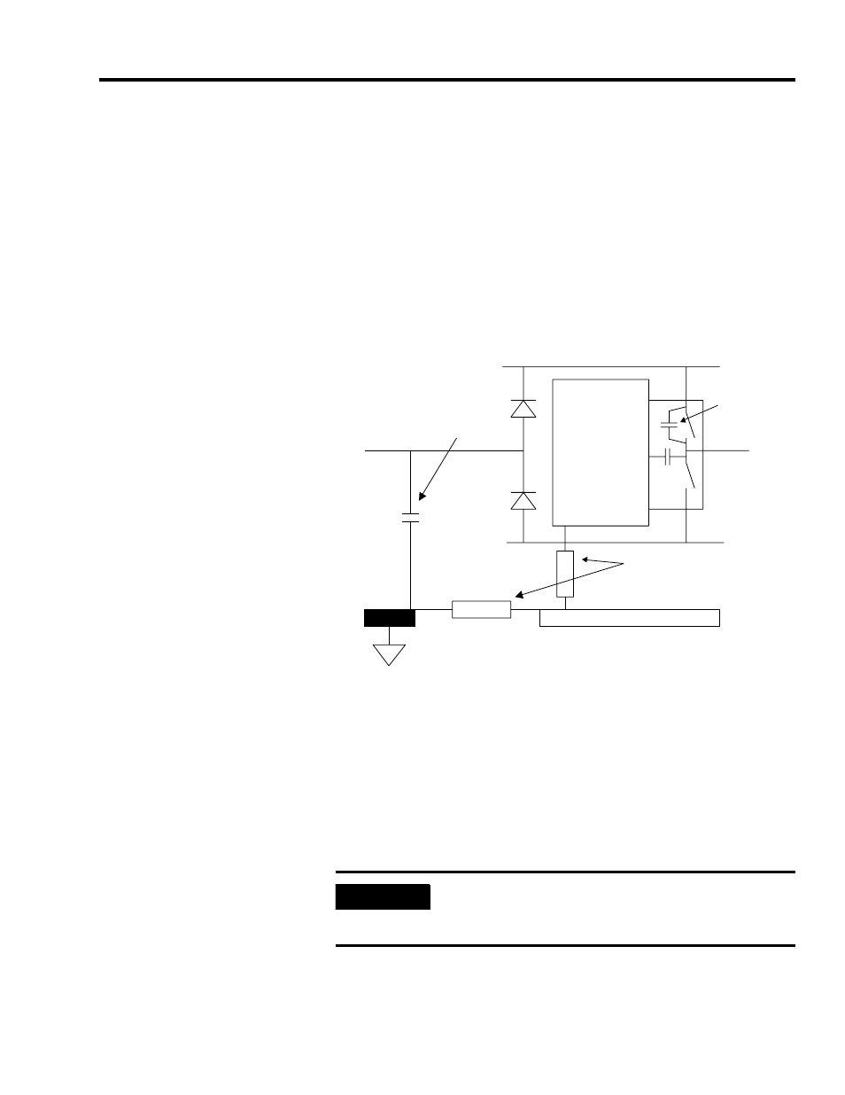
Noise Example 2
Stray capacitance I charges very rapidly. Current circulates via stray
capacitances H, bond G, bond F, and A. In this way, a voltage Vf + Vg
is developed between the drive chassis and true-ground.
Any remote equipment grounded to this true-ground and wired to the
drive will have this noise voltage imposed upon its incoming signal.
Figure 2.2
Switching noise affecting incoming power
Many other noise sources exist in a typical system and the advantage
of good bonding holds true for all.
The Ground Plane Principle
The purpose of High Frequency (HF) bonding is to present a defined
low impedance path for HF noise currents returning to their source.
Most textbooks on radio frequency (RF) techniques describe the
ground plane (GP) as the ultimate ground reference and an absolute
requirement for controlling RF current paths.
+600V dc
DC common
Heatsink
(connected
to chassis)
Panel
Drive
Stray
capacitance
Impedance due to
poor bonding
Transistor
block
A
F
G
Stray capacitance
to ground
AC line
H
I
IMPORTANT
Noise current must and will return to source. If a safe
path is not provided, it may return via victim wiring
and cause circuits to malfunction.