Rockwell Automation RECOMM-IBUS Interbus Communications Module User Manual
Page 73
Using Explicit Messaging (PCP Communications)
7-13
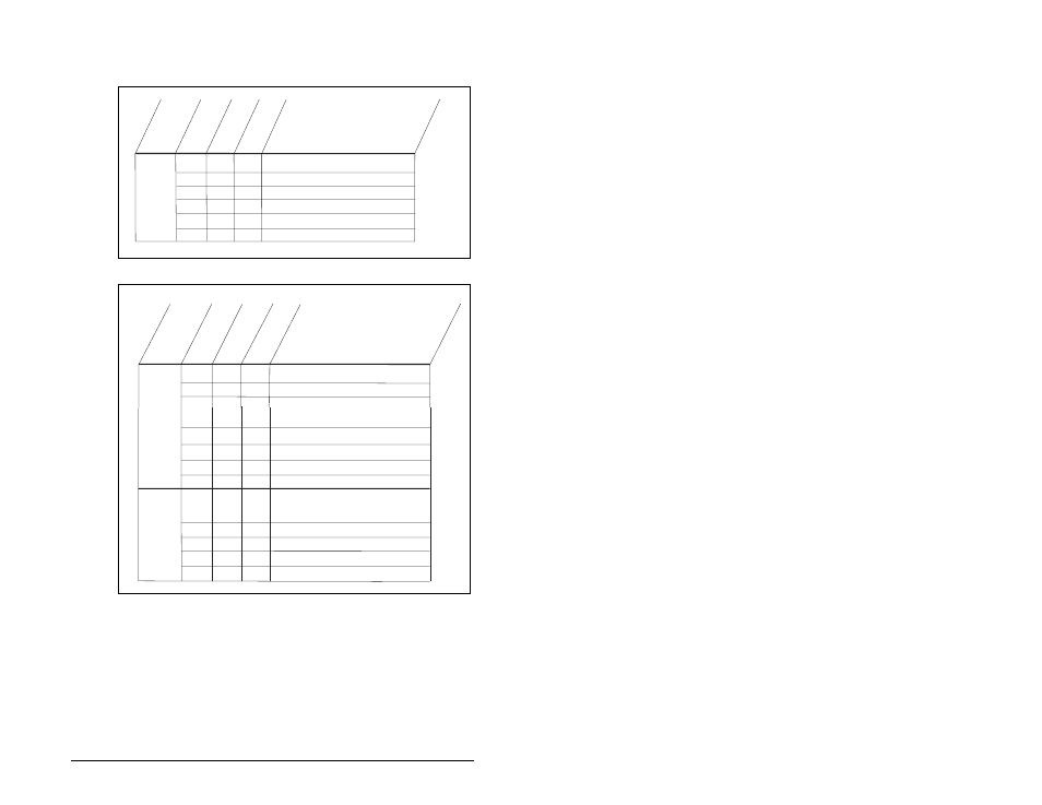
In the sample ladder logic program, the user would load these
registers before calling the subroutine to perform the PCP Write.
Figure 7.7 – Writing Comm Flt Action (6) to a RECOMM-IBUS Interbus
Module
Message
CR# =2 (Station 1.0)
N23:0
Request
2
2
SLC Addr
ess
D
es
cr
iption
Va
lu
e
(H
ex)
N23:1
0
0= PowerFlex 70 (DPI Host)
0
Va
lu
e
(D
ec
)
N23:2
106
6A
Parameter # = 106
N23:3
N23:4
2
123
0
2
7B
0
2 byte data write
Data Word 1 = 123 = 12.3 Hz
Data Word 2 not used
N23:5
0 = SP600 drive (DPI Host)
Message
Command word = 8 = PCP Write (bit 3 ON)
N23:10
Command
8
8
SLC Addr
ess
D
es
cr
iption
Va
lu
e
(H
ex)
N23:20
N23:13
N23:12
N23:11
N23:21
Reply
2
0
0
8
-32,760
CR# = 2 (Station 1.0)
Sub Index not used
Number of words following = 2
CR# = 2 (Station 1.0)
2FBB
2
0
8
8008
N23:16
0
Va
lu
e
(D
ec
)
Result = 0 (success)
N23:23
0
2
2
0
2
2
N23:22
N23:24
"8000" (bit 15 ON) indicates Reply message present
Status word:
"0008" (bit 3 ON) echo's the command (PCP Write)
2FB6h is the start of the 20-COMM-I parameters (Pr.1)
Index = 2FB5h+6h = Parameter 6 [Comm Flt Action
6 hex = 6 dec = Parameter 6 [Comm Flt Action]
Echo of the Command Word (PCP Write)
N23:14
N23:15
1
512
200
1
Data word 2 not used
Data Word 1 (upper byte) = 2 (Zero Data)
1 byte of data following
12219
Index = 2FB5h+6h = Comm Flt Action (6)
2FB6h is the start of RECOMM-IBUS parameters
6 hex = 6 dec = Comm Flt Action (6)