Rockwell Automation 57C332 AutoMax Power Supply Module and Racks User Manual
Page 24
3Ć8
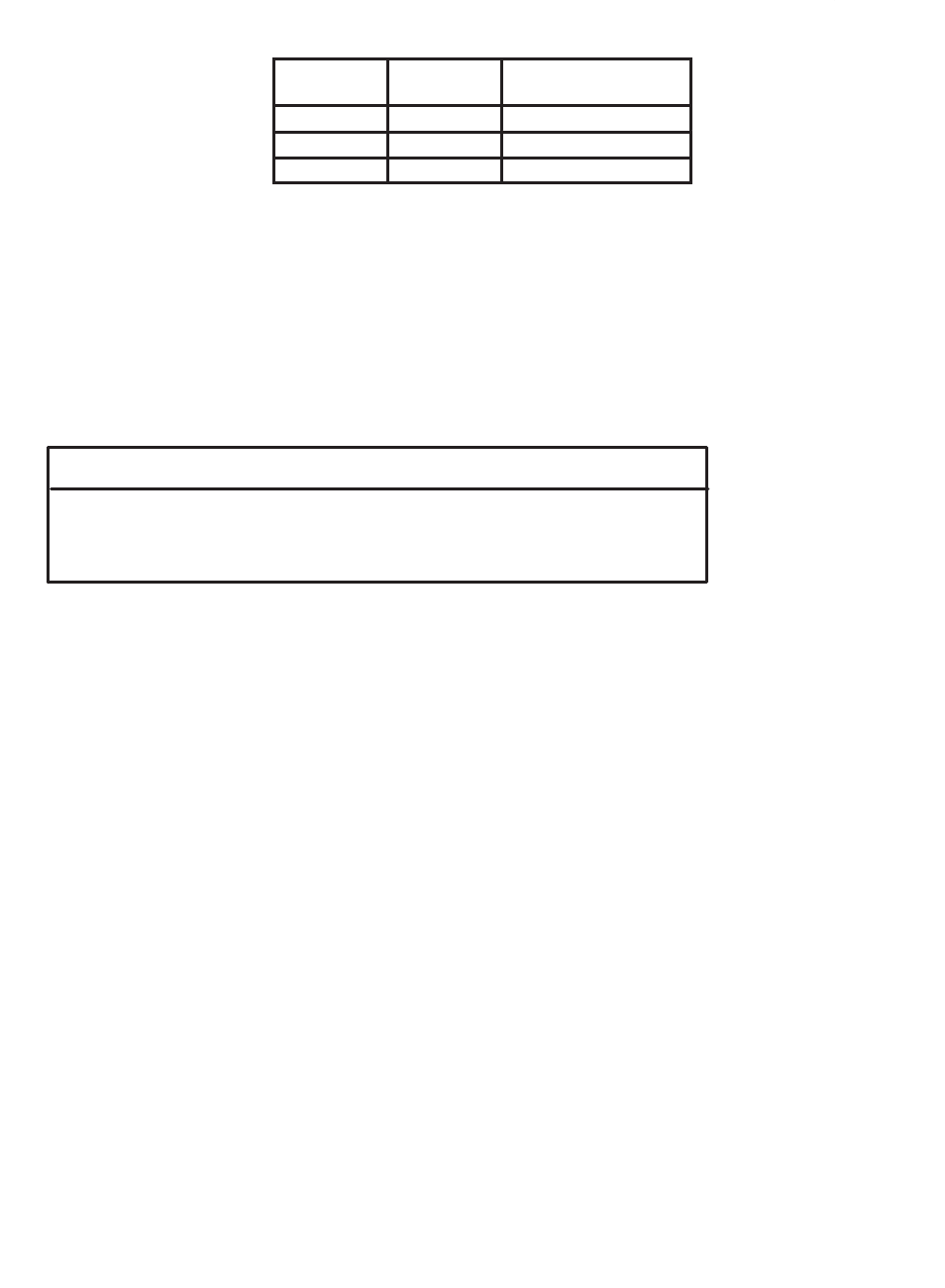
Wire Color
Wire Label
Power Supply
Faceplate Connector
black
L2
L2
orange
L1
L1
green
-
GND
The wires labeled L2 and L1 should remain twisted
together as much as possible between the Rack and
the Power Supply module.
Step 11. Using a screwdriver, reĆattach the nameplate bracket to
the base of the rack.
Step 12. Turn on power to the system.
Step 13. Verify the installation by connecting the personal computer
to the port labeled PROGRAMMER/PORT B" on the
leftmost Processor in the Rack and running the ReSource
programming software. Try to read from or write to the
registers on each of the modules in the Rack.
WARNING
WHEN WRITING TO OUTPUTS, BE CAREFUL TO INSURE THAT NO UNEXPECTED
MACHINE MOTION WILL RESULT. FAILURE TO OBSERVE THIS PRECAUTION
COULD RESULT IN BODILYINJURYOR DAMAGE TO EQUIPMENT.
Refer to the instruction manuals describing the specific
hardware in the installation for more information.