4 rack electrical description – Rockwell Automation 57C332 AutoMax Power Supply Module and Racks User Manual
Page 16
2Ć8
2.4
Rack Electrical Description
The Multibus backplane of the Rack supports two sets of bus lines
that serve as the electrical connection for all slots in the Rack. The P1
bus, the larger of the two electrical connectors, conforms to the IEEE
Microcomputer System Bus Standard for the P796 bus, compliance
level D16M20I16. This bus is used for communication and control
signals among the different modules in the Rack. The P2 bus, the
smaller of the two backplane electrical connectors, follows a Reliance
pin assignment as permitted by the IEEE P796 standard. The P2 bus
is used for functions such as determining the slot number of the
module. See Appendix C for a description of the pins on the Rack
backplane. See JĆ3649, JĆ3750, or J2Ć3045 for guidelines on using
nonĆReliance modules in the Rack.
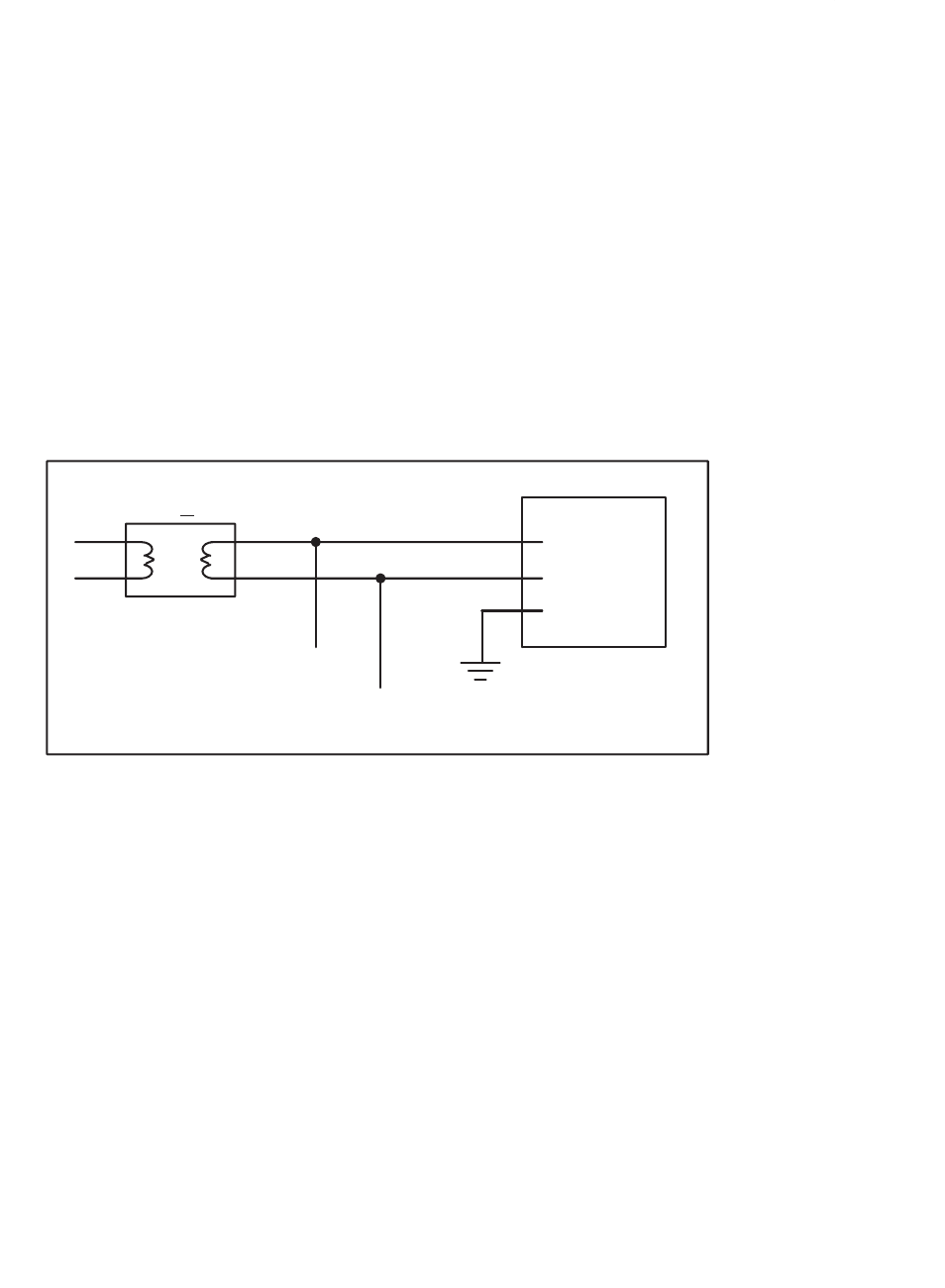
The AC line filter on the Rack filters the incoming power signal before
it is transmitted to the Power Supply module. The surge protector
provides power supply protection from power surges. No other
connections to the AC line are permitted between the line filter and
the Power Supply module. See figure 2.7 for a typical input power
signal.
KVA < 50
188
189
RACK
115 VAC
HOT
115 VAC
NEUTRAL
Figure 2.7Ć Typical Input Power Connections