Communications port test, Communications port test -12 – Rockwell Automation 2707-MVH232_MVP232 MicroView Operator Interface Module User Manual
Page 66
Publication 2707-UM005B-EN-P
8-12 Troubleshooting and Maintenance
Communications Port Test
Use the communications test to verify the operation of the MicroView
communications port.
During the communications test, the MicroView must be supplied with
11 to 25 VDC through the power port. The following power adapters
are recommended:
•
Catalog No. 2707-PS120, MicroView 120VAC Power Adapter
•
Catalog No. 2707-PS220, MicroView 220VAC Power Adapter
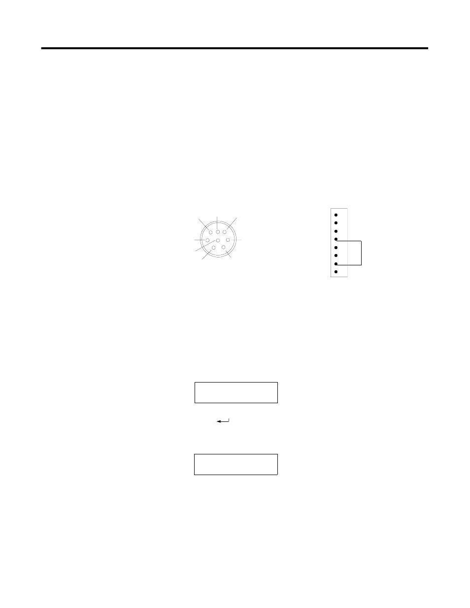
The communications test requires a loopback connector. You can construct a simple
loopback connector as follows:
To test the communications port:
1. Connect the Loopback connector to the communications port of
the MicroView (Pins 4 and 7).
2. Connect an AC to DC power adapter to the power port.
3. Use the [NEXT] and [PREV] keys to display “Comm Port” on the
test screen.
4. Press [
] to initiate the test.
The MicroView will continuously send out and receive a
message at the communications port and display:
5. Press any key to terminate the communications test.
Loopback
Connector
Pins 4 and 7
MicroView RS-232
Communications Port
MicroView RS-232
Communications Port
+24V dc
DC Com
Data In (RXD)
Data Out (TXD)
Signal Ground
8-Pin Female C DIN Connector
1
2
3
6
7
8
5
4
1
2
3
4
5
6
7
8
Diagnostic Tests
Comm Port
COMM Self Loop
Any Key to Cont.