Rockwell Automation 2090-xxx Fiber Optic Cable Installation and Handling Instructions User Manual
Page 9
Fiber Optic Cable Installation and Handling Instructions 9
Publication 2090-IN010C-EN-P – April 2005
3. Verify that optometer is set to measure appropriate wavelength and
attenuation in dB.
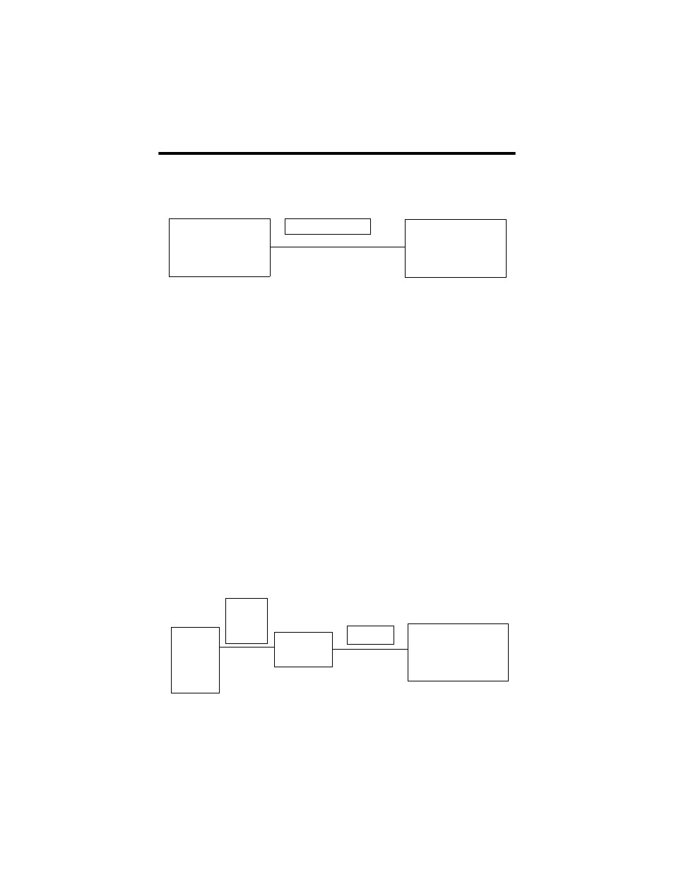
Figure 8 Attenuation Measurement
4. Securely connect test cable between source and optometer.
5. Use the dB value on the optometer to verify that the cable under test
is within specification listed in the table for that specific catalog
number.
6. Reverse the cable and test again starting at step 2.
Cable Attenuation Measurement with Bulkhead Connector
1. Inspect ends of cable for proper termination. Clean ends of fiber.
2. Turn on light Source
3. Securely connect appropriate reference cable corresponding to the
type of cable to be tested.
• POF reference cable used for testing POF cable
• HCS reference cable used for testing HCS cable
4. Securely connect bulkhead connector to reference cable.
5. Securely connect test cable between bulkhead connector and
optometer.
Figure 9 Attenuation Measurement with Bulkhead Connector
LED Light Source
650nM nominal
Optometer measuring
loss in dB
Test Cable
LED Light
Source
650nM
nominal
Optometer measuring
loss in dB
Test Cable
1 meter
reference
cable
Coupler
2090-s-blhd