Programming example – Rockwell Automation 2705 REDIPANEL KEYPAD MODULE USER MANUAL User Manual
Page 53
Chapter 7
Programming
7–15
In the programming example shown in Figure 7.7, you’ll notice the length
has been set for (12), 8 words for the block transfer utility functions and 4
words for the Keypad Modules configured for 1/2 rack. The DATA FILE for
the block transfer read instruction begins at N11:0. This means the addresses
in the ladder logic, for the keypad input, will begin with N11:8/00. The
DATA FILE for the block transfer write instruction begins at N12:0. This
means the addresses in the ladder logic, for the keypad output, will begin
with N12:8/00.
Programming Example
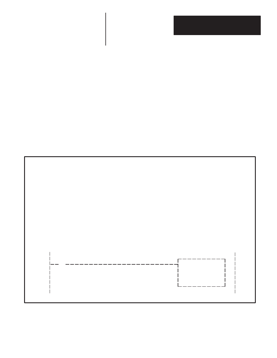
Figure 7.8 shows an example of what the instruction addresses for the
RediPANEL Keypad Module would look like in the ladder logic, given the
configuration shown in Figure 7.7. The first 8 words of files N11: and N12:
have been reserved for the sub I/O scanner utility words.
Figure 7.8
PLC–5/15 and Sub–Scanner Ladder Logic Example
Output Addresses
N12:00/00 - N12:07/15 (8 Words)
Reserved for Sub–Scanner Utility Functions.
N12:08/00 - N12:11/15 (4 Words)
1/2 rack reserved for output image table of the
keypad module, module group 0–3
RediPANEL
Address Profile
Input Addresses
N11:00/00 - N11:07/15 (8 Words)
Reserved for Sub–Scanner Utility Functions.
N11:08/00 - N11:11/15 (4 Words)
1/2 rack reserved for input image table of the
keypad module, module groups 0–3
Keypad Module
F1 Push Button
10
Moves T4:0 preset to
keypad data display
N11:08
] [
MOVE
Source
T4:0.PRE
15
Dest
N12:09
0
MOV