Setting switch bank #3, Sw–2 – Rockwell Automation 2705 REDIPANEL KEYPAD MODULE USER MANUAL User Manual
Page 30
Chapter 5
Selecting Options
5–5
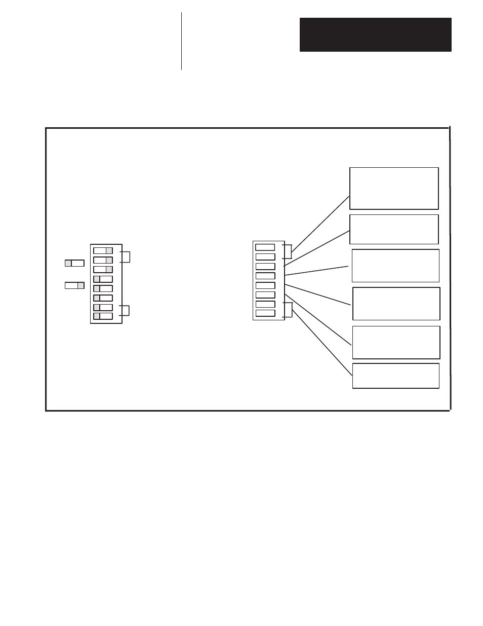
Figure 5.6 gives the switch functions and settings for Switch Bank #3. These
switch bank #3 settings are for all PLC’s.
Figure 5.5
Setting Switch Bank #2
ON
OFF
ON
OFF
SW–2
ON
OFF
SW–2
Example
1
2
3
4
5
6
7
8
1
2
3
4
5
6
7
8
RACK SIZE
1/4
1–ON
2–ON
1/2
1–ON
2–OFF
3/4
1–OFF
2–ON
Full
1–OFF
2–OFF
STORED MESSAGE
ENABLED
4–OFF
DISABLED
4–ON
SPLIT DISPALY
XT
5–OFF
AT
5–ON
KEYBOARD STYLE *
TRACKING
6–OFF
BCD
6–ON
SMD/DEST FORMAT
SWITCHES 7&8
NOT USED
Rack Size 1/2
NA
Stored message display ENABLED
Split display DISABLED
AT–style keyboard
DEST/SMD/Tracking
DISABLED
3–OFF
ENABLED
3–ON
Figure 5.6
Setting Switch Bank
#3
Enable STORED MESSAGE to be able to store and retrieve messages on the
EEPROM inside the keypad module. If STORED MESSAGE is disabled,
messages can only be retrieved from PLC memory.
Enable SPLIT DISPLAY to control what is displayed during operator entry.
Refer to page 6–4 for more information.
The DEST. and SMD FORMAT controls the numeric format for the
destination word in the input image table and the SMD word in the output
image table.
When BCD is selected the SMD and destination numbers are in BCD
format. When TRACKING is selected these values will follow the data type
set by DIP switches 3 and 4 on switch bank #2.
Note: On Series B Revision D or earlier modules, DIP switch 6 on switch
bank #3 is not used and the format is always BCD.
Setting Switch Bank #3