Input and output image tables – Rockwell Automation 2705 REDIPANEL KEYPAD MODULE USER MANUAL User Manual
Page 41
Chapter 7
Programming
7–3
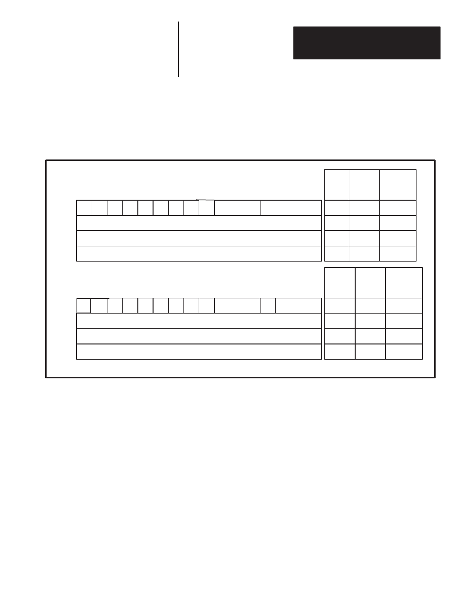
Figure 7.1 below shows the Input and Output Image Tables for the system
configuration described on Page 2.
Figure 7.1
Integer Mode, 1/2 Rack with Stored Message Display
EXAMPLE - The address for the function key “F1” in this example would be
I:020/10.
16
I:
0
1
2
3
4
5
6
7
10
11
12
13
14
15
16
17
H
EN
F6
F5
F4
F3
F2
F1
0
1
2
3
4
5
6
7
10
11
12
13
14
15
17
L6
L5
L4
L3
L2
L1
Input Image Table
Output Image Table
Two Alphanumeric Characters
Destination Bits
Dec. Pos.
DC
SDP
Dec. Pos.
Destination
Integer Data
Stored Message Display Number (SMD)
Integer Data
INPUT
RACK #
02
0
I:
02
1
I:
02
2
I:
02
3
O:
02
0
O:
02
1
O:
02
2
O:
02
3
OUTPUT
RACK #
MODULE
GROUP
(WORD)
MODULE
GROUP
(WORD)
Bits
Bits
– – – –
–
_
DM
H
The I/O image table shown in Figure 7.1, reflects the Integer data type that
the Keypad Module has been configured for. Setting the DIP switches for
Integer data type is particularly useful when using the Keypad Module with
the PLC–5, because the PLC–5 timer and counter data is stored in an Integer
format.
To display the Preset or Accumulated values of these instructions requires
only a MOVE instruction. (See Displaying Numeric Data, example #1.) If
the Keypad Module had been configured for a Binary or BCD data type, a
conversion instruction would have been needed to convert the ACCUM
value of the counter to that data type format prior to displaying it on the
Keypad Module.
Note: The input image table will only momentarily indicate a state change if
F1–F6 is pressed. This change of state may not be displayed in all instances.
Input and Output Image Tables