Setting switch bank #2, Sw–2, Figure 5.5 setting switch bank – Rockwell Automation 2705 REDIPANEL KEYPAD MODULE USER MANUAL User Manual
Page 29
Chapter 5
Selecting Options
5–4
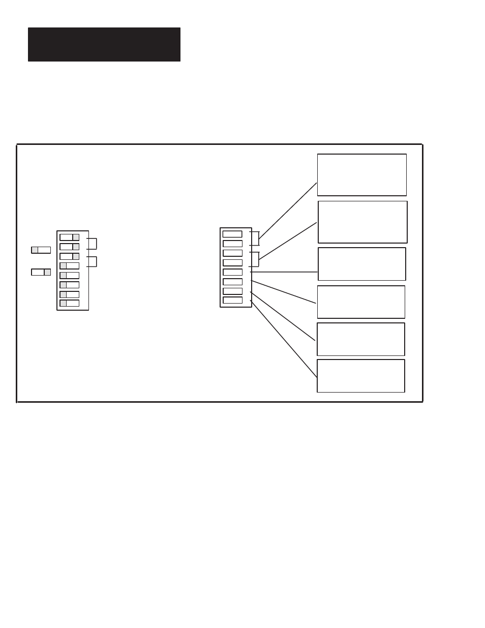
Figure 5.5 gives the switch functions and settings for switch bank #2.
Figure 5.5
Setting Switch Bank #2
ON
OFF
ON
OFF
SW–2
ON
OFF
Last Device DISABLED
Keyswitch DISABLED
Handshake DISABLED
Last State DISABLED
SW–2
Example – PLC–5/15
1
2
3
4
5
6
7
8
1
2
3
4
5
6
7
8
BAUD RATE
57.6K
1–ON
2–ON
115.2K
1–OFF
2–ON
230.4K
1–ON
2–OFF
N/A
1–OFF
2–OFF
BINARY 3–ON
4–ON
INTEGER3–ON
4–OFF
BCD
3–OFF
4–ON
N/A
3–OFF
4–OFF
DATA TYPE
ENABLED
5–OFF
DISABLED
5–ON
LAST DEVICE
DISABLED
6–OFF
ENABLED
6–ON
DESTINATION BITS
DISABLED
7–OFF
ENABLED
7–ON
HANDSHAKE
DISABLED
8–OFF
ENABLED
8–ON
LAST STATE
Baud Rate 57.6K
Integer Datatype
Figure 5.5
Setting Switch Bank
#2
Set BAUD RATE to 57.6K for PLC–5/15 and 5/25 or the module will not
communicate with the PLC.
Set LAST DEVICE to OFF position to tell the scanner module that the
Keypad module is the last device of that logical rack, not necessarily the last
device on the I/O link.
Enable HANDSHAKE to allow the use of the handshake bit which holds an
input signal on until the PLC acknowledges data receipt. If you disable
HANDSHAKE, the module uses a timed mode (100 millisecond delay) to
make sure the PLC reads the input signal. Handshaking is explained in detail
in Chapter 7.
Enable LAST STATE to lock the module up (hold the display in its last state)
if communication with the PLC is lost. If you disable LAST STATE, the
display will clear instead of locking up. When communication is
reestablished, the module updates itself, and resumes operation.
Setting Switch Bank #2