Complementary - 32 addressing – Rockwell Automation 1794-ASB/E Remote I/O Adapter Module User Manual User Manual
Page 49
3–15
Communicating with FLEX I/O Modules
Publication 1794ĆUM009D-EN-P - April 2004
Use complementary 32 point addressing when:
•
you use 32 point modules in your system
•
you need full FLEX I/O module functionality, such as delay time
selection on input modules, fuse-blown indication on the
1794-OB8EP, etc.
•
using combination modules, such as the 1794-IB16XOB16 16
in/16 out module
In complementary mode, each module position equals two I/O
groups – 2 words of input image and 2 words of output image.
00
07
10
17
00
07
10
17
0
1
2
3
4
5
6
7
I/O Group
ILL, OLL = Bits 0 thru 7 for input and output words of 32 point modules
ILH, OLH = Bits 8 thru 15 for input and output words of 32 point modules
IL, OL = Bits 0 thru 7 for input and output words for 16 and 8 point modules
IH, OH = Bits 8 thru 15 for input and output words for 16 point modules
M0ĆILH
M0ĆIHH
M0ĆOLL
M0ĆOHL
M2ĆOLH
M0ĆOLH
M0ĆOHH
Complementary 32 Addressing Example -
16 modules = 2 logical racks, N, (N+1), NC and (N + 1)C
M3ĆIHH
M2ĆOHL
M3ĆOLL
M3ĆOHL
M3ĆOLH
M3ĆOHH
M1ĆILH
M1ĆOLL
M1ĆOLL
M1ĆOLH
M1ĆOLH
M1ĆOHL
M1ĆOHL
M1ĆOHH
M1ĆOHH
M1ĆIHH
M1ĆIHH
M3ĆILH
M3ĆILH
Any module in any slot in primary chassis. Complement of primary
chassis module in complementary chassis slot.
Eight terminal bases per adapter (maximum)
1 module in primary chassis, 1 module in complementary
chassis represents 2 I/O groups.
IHL, OHL = Bits 16 thru 23 for input and output words of 32 point modules
IHH, OHH = Bits 24 thru 32 for input and output words of 32 point modules
M0ĆILL
M0ĆILL
M0ĆIHL
M0ĆIHL
M3ĆIHL
M3ĆIHL
M1ĆILL
M1ĆILL
M1ĆIHL
M1ĆIHL
M3ĆILL
M3ĆILL
M2ĆOLH
M2ĆOLH
M2ĆOHH
M2ĆOHH
00
11
22
33
44
55
66
77
I/O Group
I/O Group
00
11
22
33
44
55
66
77
I/O Group
I/O Group
00
07
10
17
00
07
10
17
0
1
2
3
4
5
6
7
I/O Group
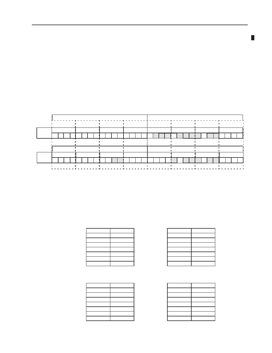
Input Image Table for Rack N and NC
Output Image Table for Rack N and NC
M0ĆILH
M0ĆIHH
CM0ĆOLL
CM0ĆOHL
CM2ĆOL
CM0ĆOLH
CM0ĆOHH
CM3ĆIHH
M3ĆOLL
M3ĆOHL
M3ĆOLH
M3ĆOHH
CM1ĆILH
CM1ĆIHH
CM3ĆILH
M0ĆILL
CM3ĆIHL
CM1ĆILL
CM1ĆIHL
CM3ĆILL
CM2ĆOH
M1ĆOLL
M1ĆOHL
M1ĆOLH
M1ĆOHH
0
1
2
3
4
5
6
7
M3ĆIHH
M1ĆILH
M3ĆILH
M3ĆILH
M4ĆMSB
M3ĆIHL
M3ĆIHL
M1ĆILL
M1ĆILL
M3ĆILL
M3ĆILL
M2ĆILL
M2ĆILL
00
07
10
17
0
1
2
3
4
5
6
7
I/O Group
Input Image Table for Rack N+1 and (N+1)C
M7ĆIHH
M7ĆILH
M7ĆIHL
M7ĆILL
M0
M1
M2
M3
M4
M5
M6
M7
ASB/E
CĆM0
CĆM1
CĆM2
CĆM3
CĆM4
CĆM5
CĆM6
CĆM7
ASB/E
Primary
Comp.
Group 0 & 1
Legal Module Placement in 32Ćpoint Complementary
Input 32
Output 32
Empty
Output 32
Output 8
Input 32
Analog
Analog
Output 32
Output 32
Input 32 Output 16
Input 32
Empty
Analog
Input 8
IHH IHL
ILH ILL
OHH OHL
OLH OLL
IHH IHL
ILH ILL
OHH OHL
OLH OLL
OL
OH OL
OHH OHL
OLH OLL
OL
IHH IHL
ILH ILL
IL
OHH OHL
OLH OLL
IHH IHL
ILH ILL
0
1
2
3
4
5
6
7
M3ĆIHH
M5ĆMCB
M3ĆILH
M3ĆILH
CM5ĆMCB
M3ĆIHL
M3ĆIHL
M1ĆIHL
M1ĆIHL
M3ĆILL
M3ĆILL
M2ĆILL
M2ĆILL
00
07
10
17
0
1
2
3
4
5
6
7
I/O Group
Output Image Table for Rack N+1 and (N+1)C
CM7ĆOHH
CM7ĆOLH
CM7ĆOHL
CM7ĆOLL
MSB
MCB
MSB
MCB
Any input module complemented by an output module or empty slot.
Any output module complemented by an input module or empty slot.
Any block transfer module complemented with a block transfer
module or empty slot.
An empty slot complemented by an empty slot, input
or output module
Note: Shaded areas represent unavailable data
CM5ĆMSB
M5ĆMSB
CM6ĆIL
M6ĆOL
M4ĆMCB
Group 2 & 3
Group 4 & 5
Group 6 & 7
Group 0 & 1
Group 2 & 3
Group 4 & 5
Group 6 & 7
Rack N
Rack (N + 1)
Rack NC
Rack (N + 1)C
MSB
MCB
Complementary - 32
Addressing