Rockwell Automation 1794-ASB/E Remote I/O Adapter Module User Manual User Manual
Page 10
Using This Manual
P–4
Publication 1794ĆUM009D-EN-P - April 2004
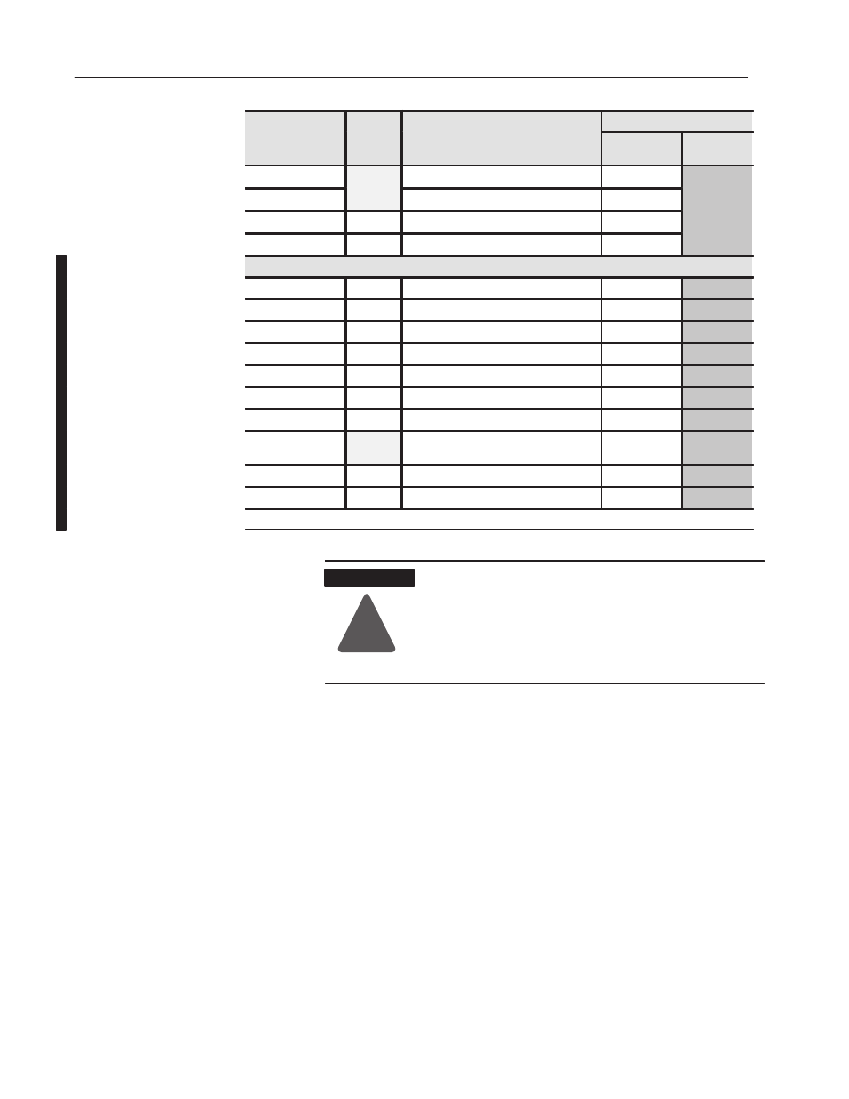
Publications
Description
Voltage
Catalog
Number
User
Manual
Installation
Instructions
Description
Voltage
Catalog
Number
1794ĆCE1, ĆCE3
Extender Cables
1794Ć5.12
1794ĆNM1
Mounting Kit
1794Ć5.13
1794ĆPS13
24V dc
Power Supply
1794Ć5.35
1794ĆPS3
24V dc
Power Supply
1794Ć5.71
FLEX Ex
1797ĆIBN16
See note 16 NAMUR Digital Input Module
1794ĆIN072
1797ĆOB4D
See note 4 NI, Ex Source Digital Output Module
1794Ć5.6
1797ĆIE8
See note 8 Selectable Input Module
1794Ć5.5
1797ĆIE8NF
See note 8 Selectable Filter Analog Input Module
1794Ć5.31
1797ĆOE4
See note Selectable Analog 4 Output Module
1794Ć5.3
1797ĆIRT8
See note 8 Thermocouple/RTD Input Module
1794Ć5.4
1797ĆIJ2
See note 2 Frequency Input Module
1794Ć5.9
1797ĆTB3
1797ĆTB3S
3Ćwire Screw Clamp Terminal Base
3Ćwire Spring Clamp Terminal Base
1797Ć5.1
1797Ć5.2
1797ĆBIC
See note I.S. Bus Isolator
1797Ć5.13
1797ĆCEC
See note FLEX Ex Bus Connector
1797Ć5.13
Note: Intrinsically Safe Voltage
ATTENTION
!
FLEX I/O is grounded through the DIN rail to chassis
ground. Use zinc plated, yellow chromated steel DIN
rail to assure proper grounding. Using other DIN rail
materials (e.g. aluminum, plastic, etc.) which can
corrode, oxidize or are poor conductors can result in
improper or intermittent platform grounding.