Wiring – Rockwell Automation 1794-ASB/E Remote I/O Adapter Module User Manual User Manual
Page 25
2–7
Installing Your Remote I/O Adapter Module
Publication 1794ĆUM009D-EN-P - April 2004
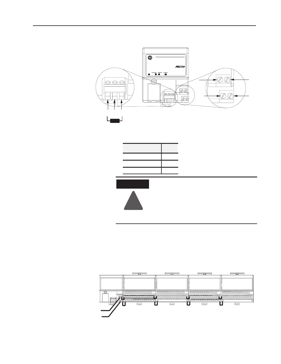
Connect external wiring to the remote I/O adapter as shown below.
1 SH 2
B
C
D
A
20131
24V
COM
AllenĆBradley
24 VDC
POWER SUPPLY
RIO ADAPTER
1794-ASB
ADAPTER
ACTIVE FAULT
LOCAL
FAULT
Termination resistor (if required)
82
Ω
or 150
Ω
(refer to your processor
documentation for size and usage)
PWR
1. Connect the remote I/O cable to the removable plug-in remote
I/O connector.
Connect
To
Blue Wire - RIO
1
Shield Wire - RIO
SH
Clear Wire - RIO
2
ATTENTION
!
If this is the last adapter in your FLEX I/O
system, or the last adapter on the remote I/O link,
you must use a termination resistor across
terminals 1 and 2 on the remote I/O connector.
Refer to the information supplied with the
processor being used for information on the size
of the resistor.
2. Connect +24V dc input to the left side of the lower connector
terminal A.
3. Connect 24V common to the left side of the upper connector
terminal B.
4. Connections C and D are used to pass 24V dc power and
common to the next module in the series (if required).
Wiring when total current draw is less than 10A
DaisyĆchaining
24Vdc
Note: Refer to the individual instructions for each module for actual wiring information.
Note: Modules must be either all analog or all discrete. Do not mix analog
and discrete modules when using the daisyĆchain wiring scheme.
For Example:
Wiring