Standard addressing – Rockwell Automation 1794-ASB/E Remote I/O Adapter Module User Manual User Manual
Page 40
3–6
Communicating with FLEX I/O Modules
Publication 1794ĆUM009D-EN-P - April 2004
Use standard addressing when:
•
you need full FLEX I/O module functionality, such as delay time
selection on input modules, fuse-blown indication on the
1794-OB8EP, etc.
•
using combination modules, such as the 1794-IB10XOB6 10 in/6
out module
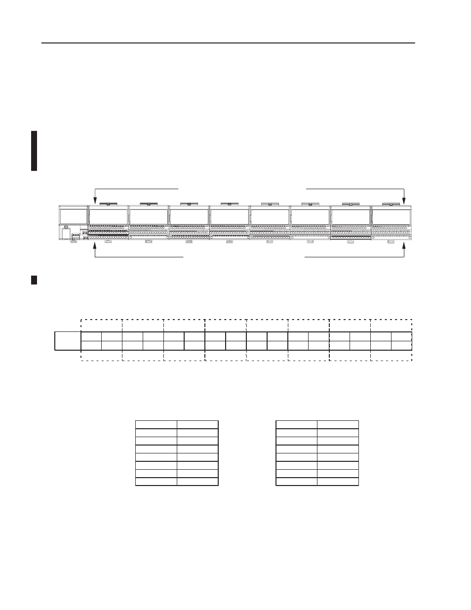
In standard mode, each module position equals one I/O group – 1
word of input image and 1 word of output image. If 32-pt input or
output modules are used, only the lower 16 bits are available. All 32
bits of the 32–pt combination modules are available.
Any combination of digital or analog modules.
Eight terminal bases per adapter (maximum)
Adapter
20128
Each terminal base represents 1 I/O group
Input
Output
Input
Output
Analog
Analog
Output
Input
Standard Addressing
00
07
10
17
00
07
10
17
0
1
2
3
4
5
6
7
I/O Group
Input Image Table
Output Image Table
M0
M1
M2
M3
M4
M5
M6
M7
IL = Input Low Byte
IH = Input High Byte
OL = Output Low Byte
OH = Output High Byte
MCB = Module Control Byte (output data)
MSB = Module Status Byte (input data)
ASB/E
IH
IL
IH
IL
OH
OL
IB16
IB16
IB16
OH
OL
M0ĆIL
M1ĆIL
M4ĆMSB
M0ĆIH
M1ĆIH
M0ĆOL
M1ĆOL
M4ĆMCB
M0ĆOH
M1ĆOH
MCB
MSB
OB16
MCB
MSB
IE8
IE8
OH
OL
IH
IL
OB16
OB16
Standard AddressingExample
I/O Group 0
I/O Group 1
I/O Group 2
I/O Group 3
- 8 modules = 1 logical rack = 8 I/O groups
I/O Group 4
I/O Group 5
I/O Group 6
I/O Group 7
M5ĆMSB
M7ĆIL
M7ĆIH
M5ĆMCB
M6ĆOL
M7ĆOL
M6ĆOH
M7ĆOH
M2ĆIL
M2ĆIH
M2ĆOL
M2ĆOH
M3ĆOL
M3ĆOH
M3ĆIL
M3ĆIH
M6ĆIL
M6ĆIH
1 module position is an I/O group
Legal Module Placement in Standard Addressing
Any module in any slot
OH
OL
OH
OL
OH
OL
IH
IL
IH
IL
IH
IL
Standard Addressing