Analog (block transfer) modules – Rockwell Automation 1794-ASB/E Remote I/O Adapter Module User Manual User Manual
Page 39
3–5
Communicating with FLEX I/O Modules
Publication 1794ĆUM009D-EN-P - April 2004
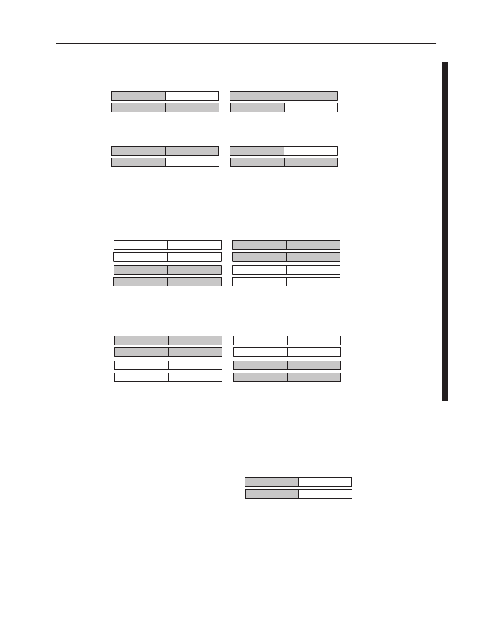
Note: Shaded areas represent data not accessible by the processor.
Input Word
Output Word
8 Bits
8 Bits
8 Bits
8 Bits
8 Bits
8 Bits
8 Bits
8 Bits
Complementary Mode
8Ćpt Density
8 bits of input OR
8 bits of output available
Input Word
Output Word
8 Bits
8 Bits
8 Bits
8 Bits
8 Bits
8 Bits
8 Bits
8 Bits
Primary Chassis
Complement Chassis
8Ćbit Input modules complemented by 8Ćbit output modules
Input Word 0
Input Word 1
Complementary - 32 Mode
32-pt density
8 Bits
8 Bits
8 Bits
8 Bits
32 bits of input OR
32 bits of output available
Input ModuleExample
Output ModuleExample
Output Word 0
Output Word 1
8 Bits
8 Bits
8 Bits
8 Bits
Input Word 0
Input Word 1
Complementary - 32 Mode
32 bits of input OR
32 bits of output available
8 Bits
8 Bits
8 Bits
8 Bits
Input ModuleExample
Output ModuleExample
Output Word 0
Output Word 1
8 Bits
8 Bits
8 Bits
8 Bits
Complement Chassis
Primary Chassis
8 Bits
8 Bits
8 Bits
8 Bits
8 Bits
8 Bits
8 Bits
8 Bits
8 Bits
8 Bits
8 Bits
8 Bits
8 Bits
8 Bits
8 Bits
8 Bits
Note: If 16Ćpt or 32Ćpt modules are used in 8Ćpt complementary addressing,
only theinformation in thelowest bytewill besent to theprocessor.
Input ModuleExample
Output ModuleExample
Input ModuleExample
Output ModuleExample
32Ćbit Input modules complemented by 32Ćbit output modules
Analog modules use block transfers, which require 1 byte (8 bits) of
input image for the module status byte, and 1 byte (8 bits) of output
image for the module control byte. This is true for any addressing
mode selected.
Input Word
Output Word
Any Mode
Block transfers require
8 bits of input imageand
8 bits of output image
8 Bits
8 Bits
Input or Output Example
MSB
MCB
Analog (Block Transfer)
Modules