Setting the mode selection switches – Rockwell Automation 1794-ASB/E Remote I/O Adapter Module User Manual User Manual
Page 30
2–12
Installing Your Remote I/O Adapter Module
Publication 1794ĆUM009D-EN-P - April 2004
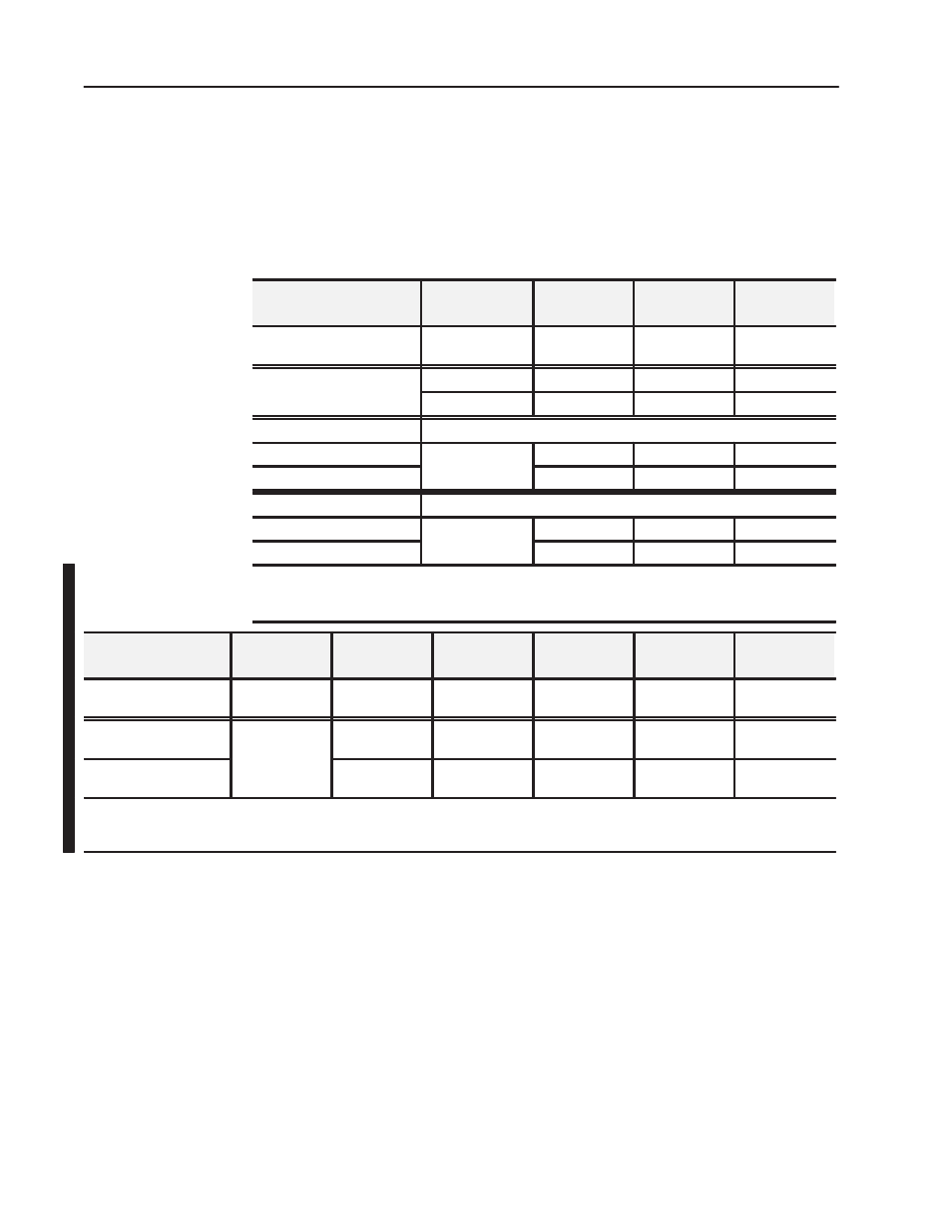
Set the mode selection switches for the desired mode as follows.
1. Lift the hinged switch cover on the front of the adapter to expose
the switches.
2. Set the switches as shown below.
3. Cycle power to the adapter to activate the settings.
When Using this
Addressing Mode
And
Mode Switch 2
S1Ć1
Mode Switch 1
S2Ć5
Mode Switch 0
S2Ć8
Standard
1
8 and/or 16Ć point
modules
See note 1
ON
ON
Compact
2
8Ćpoint modules
OFF
ON
OFF
16Ćpoint modules
ON
ON
OFF
Complementary
See Complementary Rack Addressing Table, page2-15
Primary chassis
8Ćpoint modules
OFF
OFF
ON
Complementary chassis
8Ćpoint modules
ON
OFF
ON
Complementary
See Complementary Rack Addressing Table, page 2-15
Primary chassis
16Ćpoint modules
2
OFF
OFF
OFF
Complementary chassis
16Ćpoint modules
2
ON
OFF
OFF
1
In standard mode, this switch retains its function as switch position 1 of rack addressing. In Standard mode, the module is functionally
interchangeable with a 1794ĆASB series A or B adapter.
2
In compact mode, 32-point modules appear as 8 or 16-point modules.
3
When programming block transfers, address analog modules as module 0 if switch S1Ć1 is on; module 1 if switch S1Ć1 is off.
When Using this
Addressing Mode
And
Mode Switch 0
S2-8
Mode Switch 1
S2Ć5
Mode Switch 2
S1-1
Mode Switch 3
S2-3
Mode Switch 4
S2Ć4
Standard - 32
1
8, 16 and/or 32Ć
point modules
ON
ON
See note 1
OFF
OFF
Complementary - 32
Primary chassis
2
8, 16 and/or 32Ć
OFF
OFF
OFF
OFF
OFF
Complementary - 32
Complementary chassis
2
point modules
OFF
OFF
ON
OFF
OFF
1
In Standard - 32 mode, any module in the chassis occupies 32 input points and 32 output points in the Input/Output data table.
2
In Complementary - 32 mode, any module in the chassis occupies 32 input points or 32 output points in the Input/Output data table. If using an 8 point or 16 point module, the unused
points in the data table are zeroed out.
Setting the Mode Selection
Switches