Complementary addressing mode – Rockwell Automation 1794-ASB/E Remote I/O Adapter Module User Manual User Manual
Page 46
3–12
Communicating with FLEX I/O Modules
Publication 1794ĆUM009D-EN-P - April 2004
Use complementary addressing when:
•
you are not using combination modules
•
you don’t need all the features of FLEX I/O modules
•
you can locate equal numbers of input and output modules in
separate chassis
•
you want more efficient use of the input/output image table
Complementary Mode - 16Ćpoint
Complementary mode maximizes 2 chassis I/O image table usage
when input modules are installed in 1 chassis, and output modules
are installed in another chassis. This mode allows 2 modules to
occupy a single I/O group.
In complementary mode, with 16-point density, 1 digital input
module in the primary chassis, and 1 digital output module in the
complementary chassis, or vice versa, form an I/O group. In
addition, analog modules can be complemented by another analog
module or an empty base. If 32-pt modules are used, only the lowest
16 bits will be available.
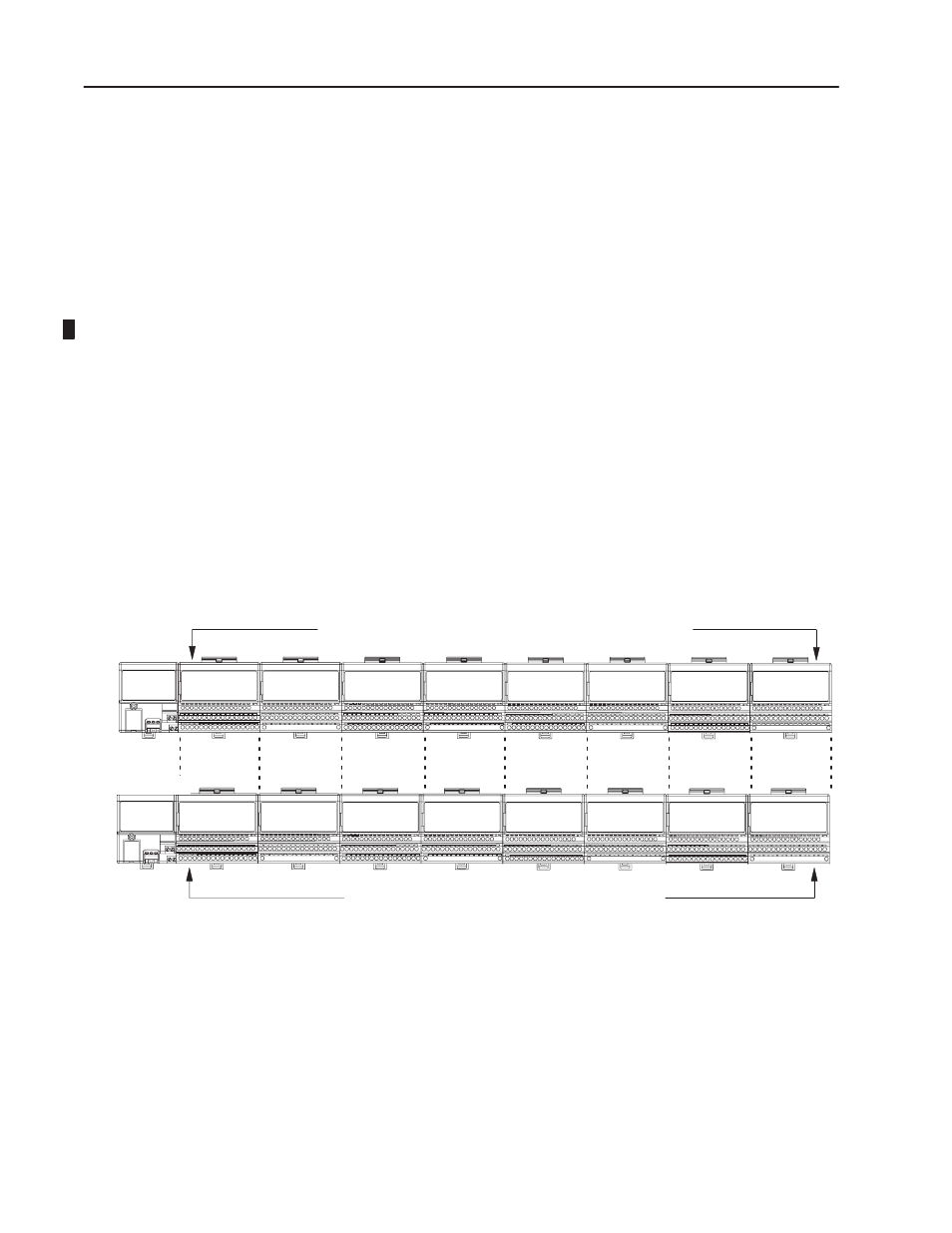
Any combination of digital or analog modules.
Adapter
Input
Complement of modules in primary chassis, or analog or empty for analog.
Eight terminal bases per adapter (maximum)
Adapter
20128
2 modules, 1 in primary and 1 in complement represent 1 I/O group
Output
Empty
Analog
Primary
Analog
Analog
Input
Input
Output
Input
Output
Output
Output
Output
I/O Group 1 I/O Group 2
I/O Group 3 I/O Group 4
I/O Group 5
I/O Group 6
I/O Group 7
I/O Group 0
16Ćpoint Complementary Addressing
Empty
Input
Note: When programming block transfers, address analog modules as module 0 if switch S1Ć1 is on; module 1 if switch S1Ć1 is off.
S1Ć1 OFF
S1Ć1 ON
Complementary
Complementary
Addressing Mode